


1.6.2 Lecture Notes The Role of Multi-terminal HVDC
Course subject(s)
1. Integration of Renewables Into the Electricity Grid
This image comes from freepik
This lecture discusses the role of multi-terminal high voltage DC power systems. This is the divided into the following topics:
- The technical structure
- Groupings and control
- Blackout prevention
Technical structure
Wind energy is one of the most promising renewable energy sources, since it is available nationwide. It is a viable energy source for both onshore and offshore. Because onshore wind energy will not be sufficient, offshore wind farms are expected to have more than 120 TW installed capacity in 2040.
The offshore generated wind energy is transferred onshore through so-called “integrated multi-terminal High Voltage Direct Current (MT-HVDC)”. The generated AC power is first converted into DC power. Then it is transferred via high power cables to the shore. Finally, the DC power is transferred back to AC energy. This is shown in the figure below.
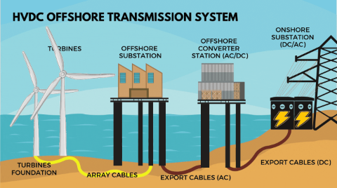
There are several reasons why HVDC is chosen for energy transfer:
- There is no need for three conductors, as would be the case for AC, which makes the transmission line cheaper.
- There are no reactive components in the transmission lines.
- The system is more controllable.
Groups and control
Offshore wind farms are organized in groups and each group is connected via a power electronic converter with grid forming capabilities. The interconnection between these power electronic converters forms the MT-HVDC power system. In this power system, each converter represents one terminal.
The power electronics converters need to be controlled such that the whole power system can operate stable at the operating points. The AC-DC converters (which are located offshore) operate in grid forming mode, which is also known as islanded mode. They control the AC voltage and the frequency of the wind turbines, such that the wind turbines operate at a stable point. The DC-AC converters (which are located onshore) should provide a stable DC voltage and active power for the HVDC. They also control the reactive power and AC voltage of the grid.
In the control design for a MT-HVDC power system, the controlling loops are given. For every power electronic converter has two different controlling loops:
- Inner controlling loops, which are used for the mitigation of the dynamical properties inside the converter.
- Outer controlling loops, which are used to control external parameters such as active and reactive AC power, DC and AC voltages, and the grid frequency.
Blackout prevention
A main challenge in MT-HVDC power systems. If one of the converters in the group has an overvoltage, this can cause a failure of that station. This overvoltage can then propagate through the systems causing the other converters to block as well. If this continues, the whole system can shut down.
A proper design of the control and protection of the MT-HVDC power systems should protect blackouts from happening and should prevent overvoltage on a station.
Conclusion
This lecture discussed the technical structure of a multi-terminal high voltage DC power system. It also discussed how the wind turbines are grouped and what the role of power electronic converters are. Finally, one of the main challenges in MT-HVDC power systems, blackouts, was discussed.
Further reading
If you are interested in this topic, you can also click on this link. Here is a document with more information about power electronic converters and about MTDC.

Technology of Intelligent and Integrated Energy Systems by TU Delft OpenCourseWare is licensed under a Creative Commons Attribution-NonCommercial-ShareAlike 4.0 International License.
Based on a work at https://online-learning.tudelft.nl/courses/technology-of-intelligent-and-integrated-energy-systems/