


1.5.1 to 1.5.5
Course subject(s)
1. Track, Train and Movement

1.5.1 Contact patch
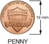
The surface of contact between wheel and rail is no more than the diameter of a penny. There where the actual diameter of the train wheel is normally around 900 mm. As small as it might be, it is the essential contact part to get into movement.
Understanding what happens in this small contact area is important for comfort, wear and safety.
The contact patch is small but the weight of a full train is on that two square cm area. This means a lot of forces are involved on both the wheel as well as the rail. In the next item we will look at the forces that the rails has to deal with to get the train into movement. To learn all about the dynamics behind the contact point between wheel and rail we have to go much more into depth. This will be discussed the more detailed Online Professional Education Course fully dedicated to track, train and motion, which will start early 2018.
 At Delft University of Technology we do many tests to understand and improve wheel/rail interface. It is rather unusual to use the same material when we talk about friction. If we look at cars the rubber tires will give up much sooner than the asphalt road surface and within the engine we use lubricant if steel and steel come together to prevent wear. In case of trains we directly put steel on steel, which makes wear inescapable, but unpredictable.
Our own rolling laboratorium measures the track in The Netherlands to test, learn and innovate together with the sector in which both our Bachelor and Master students participate.
1.5.2 Rolling resistance
From the traction force comes the maximum velocity, when this traction force is equal to all resistive forces. One well-known resistive force is the air resistance, another is the rolling resistance. The value of this rolling resistance depends on multiple things, like the use of bearings and the material of the wheels and the surface they’re riding on. The latter is interesting to look at for trains.
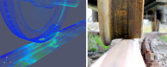 We have seen the importance of the small contact area, which causes heavy forces while driving, but to get the train out of its stationary position the track has to suffer a great deal, which is visualised in the animation below.
Pressure
It takes over 20 seconds before the wheels actually get into motion. While pressure is building up, the contact patch becomes clearly visible. Significant energy is needed to get the full combination rolling, which sometimes can result in wheel slip, when the weight is too much for the locomotive(s) to pull smoothly.
Truck vs Train
Trucks drive on a road made of asphalt or concrete and have rubber tires, which makes a great difference on multiple scales compared to trains. Looking at the properties of the materials, we know that rubber will give in first, which we can anticipate. In case of trains, this is more complex, since both train and wheel are made from steel. This makes wear difficult to predict (more on this in week 5), but it limits rolling resistance.
On roads, tires deform due to the weight of the truck, which increases resistance in rolling direction, in addition to the standard friction between rubber and asphalt. We previously saw that the contact patch of track and train is no more than the size of a penny, the contact area of a tire and the road is closer to the size of a dinner plate.
The less a wheel or tire deforms, the lower the rolling resistance will be. As trains have steel wheels, which will not deform as much, the rolling resistance that trains experience is very low, enabling them to carry much heavier loads.
As an example, imagine a load of 25 metric tonnes. A lorry will need quite a large engine of around 500 horse power or 367kW to transport this. Whereas, a train with 5000kW of power will easily move 1800 metric tonnes. The power needed to transport a metric tonne with a train is almost 5-times lower!
The reason why trains initially move so slowly has to do with rolling resistance, but this is directly related to the enormous weight of both the train and load. This combination also influences the breaking distance, which is significantly longer for trains than for other vehicles.
1.5.3 Weight, Speed and Curves
What does a guitar string have to do with a rails?
How is corrugated cardboard similar to a light rail track?
What is the similarity between a cone and a train wheel?
To explain some of the basics related to the complex forces that are at play in railways, we will use familiar shapes and items. Weight and speed are essential elements when defining a type of vehicle and its properties.
Curves
Tram and metro networks follow the city streets, which requires rather sharp turns within an existing urban grid. To be able to make these curves both their driving speed and axle weight are lower than those of regular trains, and the vehicles are also equipped with additional axles. Canting tracks (think of a race curve) are used to limit the angle of a curve and to make sure that trains don’t derail. For trams, this is rather unusual because their tracks intervene continuously with our road network, so they have to stay levelled. This also is the reason why it is impossible to add a switch within a canting track, since trains use two tracks which have to be on one level as well.
Why do you sometimes experience a ‘swinging motion’ when travelling on a train? Even on perfectly straight parts of the track? To understand where this ‘hunting’ comes from, we need to understand how a train goes through a curve first.
Hunting Explanation
In modern bogies, wheelset are mounted with suspension. This suspension dampens the ‘hunting’ behaviour of the train avoiding an unpleasant journey.
‘Steady wave’
For comfortable train travel and to limit wear we prefer a straight track. To maintain this over time is highly expensive, which is why the rail slowly transforms in a wavy surface (mainly at light rail). The visualisation below shows an extreme enlargement of this effect, looking a little like corrugated cardboard. When a train passes by with slow speed, it will follow the wavy structure, but when the same train passes driving much faster it will only make contact with the top of the waves. This results in extreme wear worsening the track status.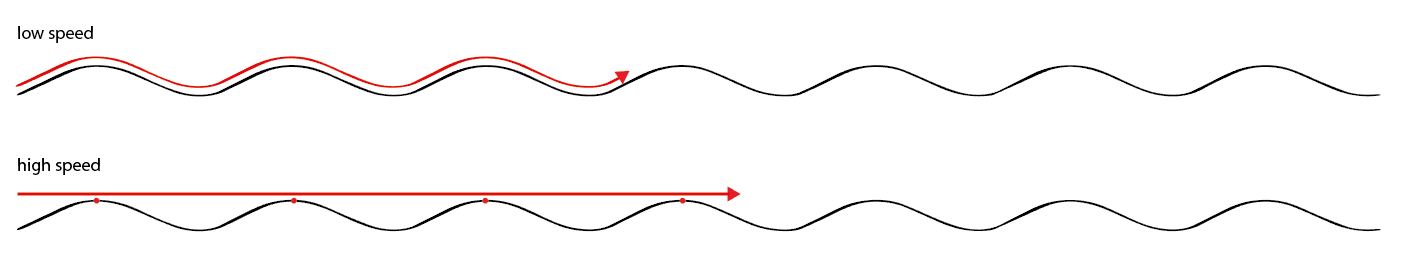
‘Moving wave’
The rails that you look up on at the station continues for thousands of kilometers, sometimes crossing multiple countries like Rotterdam to Genoa, because the ones separate parts have been welted together, creating one long rail. This can be compared with a guitar string, which, when in motion, gives a continuous vibration that can be much stronger than the train passing over it, making it come loose from the track. When heavy rail infrastructure (thick rail) is used for light rail vehicles, this worsens due to the relatively light train. It can be compared by a flee trying to walk over the earlier mentioned guitar string. While rails do not seem to vibrate that easy, the video below shows how much more a guitar string vibrates than you might have expected. Focus on how the thicker strings move more extreme than the thinner ones, which is the same with rails.
After getting more detailed insights on track, train and their interaction, are you able to answer the following question?
When comparing light and heavy rail, on which would you expect more wear and in which more cracks?
1.5.4 Switches
Switches and crossings are essential parts of the railway network. More switches means more flexibility of the network, but at the same time more switches also increases the change of one breaking down and disturbance of the railway network. Issues related to weight and speed in curves, have even more effect in switches.
In the short video below Network Rail explains very clearly how a switch works, how the train is guided either one direction or the other and the large impact on the crossing nose. We highlighted 50 seconds of animated material, but please feel to watch the full video on YouTube.
Types of Turnouts and Crossings
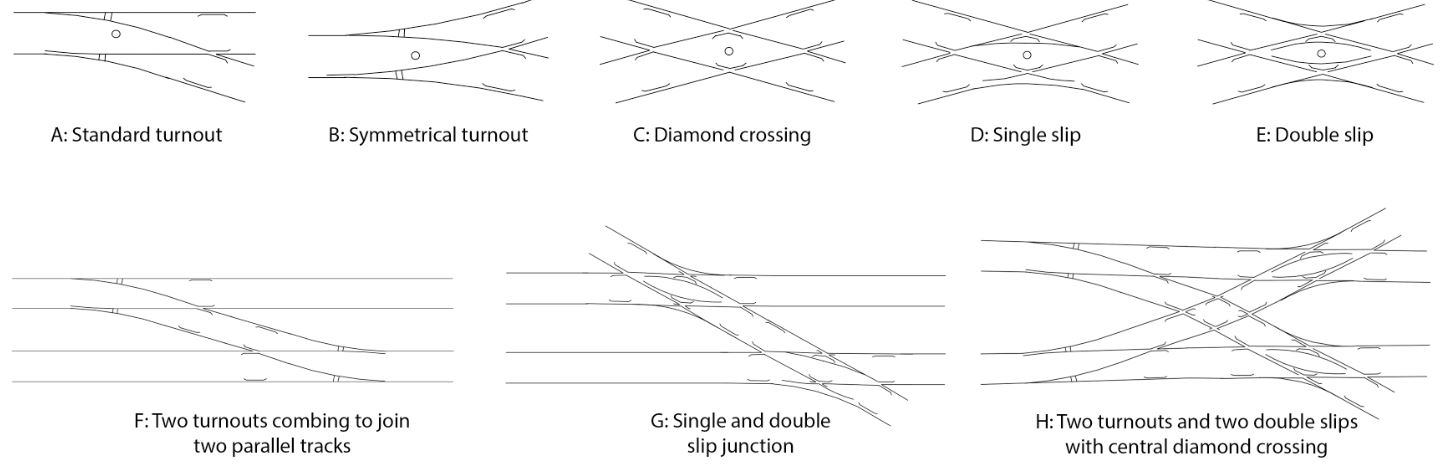
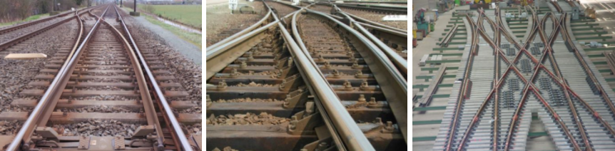 Source: MSc-lecture Dr. V.L. Markine (TU Delft)
Turnouts differ in sizes. Some commonly used ones are shown below. The number after ‘1:’ stands for the angle of intersection. The length and the maximum allowable speed to pass the turnout in the divergent direction are given below as well.
1:9 – 32 meter – 40km/h
1:12 – 38 meter – 60 km/h
1:15 – 47 meter – 80 km/h
1:34 – 99 meter – 140 km/h
To travel fast through a switch, the length of the switch should be increased and with increase of the length the construction costs and maintenance increase as well. A dilemma which will come back multiple times during this MOOC and in every situation, that has to be balanced to meet the demands of the different stakeholder.
1.5.5 Rail Lab [2]
Within the Rail Lab of Delft University of Technology we have a Wheel/rail test rig that can simulate speeds up to 240km/h. Where the scale is 1:7, all forces are balanced to this scale as well. Both track and wheels are made from actual used train wheels and rails. One week on the test track is comparable to one year on the railway network, so it is a great way to speed up new possible innovations and test results.
Below an impression of this equipment.
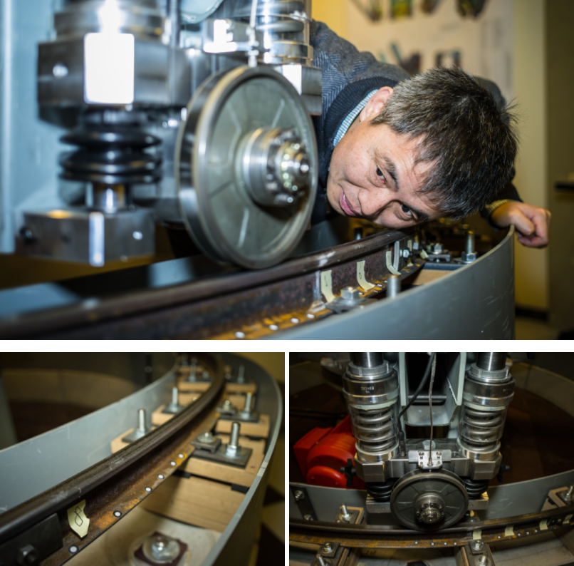 Source: TU Delft Communication CEG / Railway Engineering Group / Frank Auperlé (re-publishing only in consultation: j.q.vandijk@tudelft.nl)
More information on our Wheel/rail test rig:
>> http://railahead.tudelft.nl/testing-the-rails/
>> http://railahead.tudelft.nl/tu-opstelling-in-impact/ (Dutch)

Railway Engineering: An Integral Approach by TU Delft OpenCourseWare is licensed under a Creative Commons Attribution-NonCommercial-ShareAlike 4.0 International License.
Based on a work at https://ocw.tudelft.nl/courses/railway-engineering-integral-approach/.