


2.2.1 Forces working on the frame
Course subject(s)
Module 2. The Building Blocks of the Exoskeleton
Last module, you were briefly introduced to the main mechanical parts of the exoskeleton. We have a frame, which mimics the bones of a person. To be able to move these ‘bones’ relative to each other, there are joints in between them. These joints are powered gearing systems that enable us to create movement. If you combine the frame and joints, you roughly have the main exoskeleton structure. An exoskeleton can have a mass from about 10 kg up to 60 kg or even more. This can depend on, for example, the number of (heavy) joints and the material used in the frame. Commercially available exoskeletons usually require the pilot to have a maximum weight of 100 kg. This means that the load that is to be carried by the exoskeleton frame can be as high as 160 kg! Later this week, we will explain more about different types of joints and how we have implemented them in our exoskeleton, but let’s start with the frame first.
When designing the frame for our exoskeleton, our Frame Engineers start with a force analysis of the whole structure. It is very likely you have learned about forces at some point in school or even college.
There are a lot of forces at play in the exoskeleton. For example, the pilot exerts forces on the frame at all times. Furthermore, the backpack, containing the main electronic parts of the exoskeleton, exerts a force. And the floor exerts a force as well. Forces can be static whilst being seated, but of course, the exoskeleton is not always stationary: it is made for walking! While moving, the joints exert large rotational forces. Since we know the weight of the pilot and exoskeleton, it might sound easy to calculate a lot of the aforementioned forces. However, there are a few reasons why it’s quite complicated!
First of all, we are working with a human pilot. This means that the weight isn’t distributed over a perfect square cube with a uniform density. A human has complicated shapes and a different density at almost every spot of their body, due to different structures in the body such as bone, muscle, and fat. Drinking a bottle of water before entering the exoskeleton or eating a large lunch can increase the weight by a kilo easily. So you can’t really know where the forces created by the weight of the pilot actually are and how they are distributed. To make it even more complicated, most exoskeleton pilots rely on walking with two crutches. How much weight they rest on their arms, how far they lean forward, and how well the pilot is able to shift his/her weight that day. This all affects the forces on the exoskeleton. With so many uncertain aspects, two walks in an exoskeleton are never the same.
When designing an exoskeleton you have to make assumptions about the forces that will be exerted on the frame. Since the exoskeleton is intended to be used and moved, it is preferred to use dynamic force analysis over static force analysis. In static force analysis, it is assumed that the system does not move, and forces in all directions result in 0 Newton. That doesn’t mean there are no forces at play though! Different parts still interact and apply forces to each other. In dynamic force analysis, you take possible changes in movement into account. That means you include acceleration in your calculations since force = mass * acceleration (F = m*a; Newton’s second law). It requires estimating the acceleration of all exoskeleton parts during movement, including external and internal forces. Since this is very complicated, we at Project MARCH use static force analysis for our frame design. For every part, we assess if the dynamic forces are likely to be larger compared to the static forces. If that is plausible we assume that the maximum dynamic forces are for example 2 to 3 times larger.
For static force analysis, we need to think about possible scenarios or positions the exoskeleton can be in. For example, how large are the forces that would approximately be on the foot of the exoskeleton if the pilot would stand on only one leg? We think of worst-case scenarios, both intended and unintended. Worst-case scenarios are positions or situations at which time parts of the exoskeleton are under a very large load. Standing on only the toes of one foot is an intended worst-case scenario. It requires the exoskeleton feet to be very strong, but it is quite plausible that it happens. An unintended worst-case scenario could be that the pilot accidentally hits the stair tread with their foot. You do not want the frame to bend or break, if that happens it could harm the pilot.
These worst-case scenarios can be shown in free body diagrams (FBD’s). This is a simple representation of the object you are analyzing and provides a clear overview of all external forces at play. The reason behind your force analysis determines the choice of a free body diagram. Do you want to make an analysis of one subsystem of the exoskeleton, for instance, only the upper leg bone? Then you choose the upper leg bone as a free body diagram. To design the whole frame, your free body diagram could consist of all bones. Such an FBD might look like this:
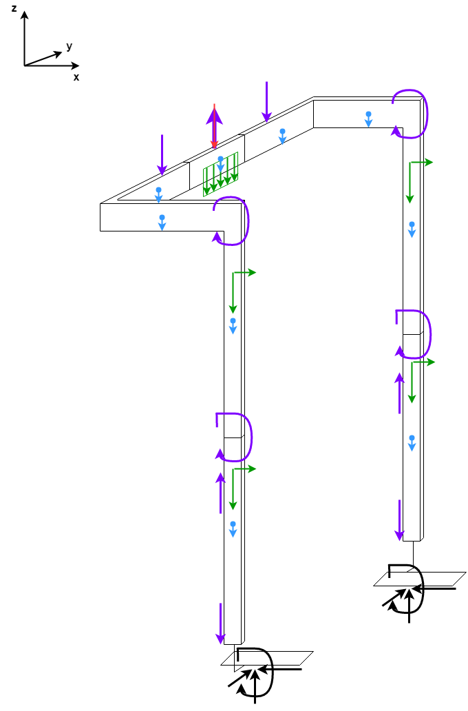
If you combine the free body diagrams created for every scenario, you now have an overview of all maximum forces exerted on all parts. There are only a few steps left till you can start manufacturing your frame!
We do not only have to think about external forces, such as gravity, normal force, and friction, but also about internal forces. Internal forces are forces within a part, caused by external forces. Internal forces are tension, compression, shear, bending moment, and torsion.
Especially the bending moment and torsion are tricky when it comes to the safety of the pilot. The long bones of the exoskeleton are susceptible to deformation when large loads are applied. These deformations have to be avoided or at least restricted to prevent them from transferring these deformations to the bone of the pilot and breaking their leg.
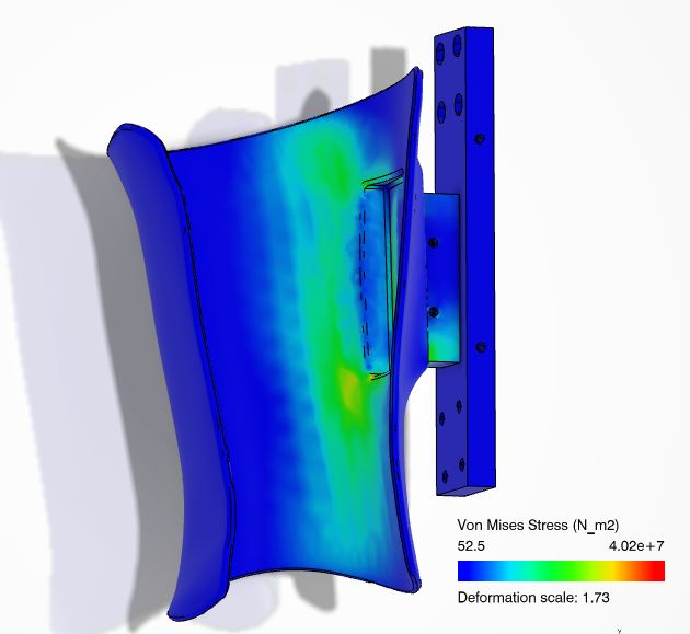
Internal forces can be determined by using the finite element method (FEM), and even though other methods are available it is quite commonly used. It’s a bit too complicated to explain FEM in this reading but feel free to do some research online! Among other things, FEM enables you to see expected deformation and internal forces based on a digital part design created in for example a Computer Aided Design program (CAD). It is displayed in an easy-to-read color scheme map of the design which you might recognize, with red parts being affected the most by the applied forces.
When performing a force analysis you are constantly faced with a paradox. It is very difficult to analyze all forces if you haven’t designed the exoskeleton frame yet, since you need the structure, sizes, materials, and connection point to determine the effect of the forces. But to be able to design the frame based on how strong it should be, you need a detailed force analysis. To be able to do one of them you need the other, and the other way around.
So how do we work around this paradox? There are a few steps we need to make to design a perfect frame. First of all, we perform a static force analysis like described above. If you have mapped all extreme scenarios you now can design an exoskeleton that can withstand these forces. You simply start somewhere with the design of the frame and with for example a CAD and FEM program you can verify if it is strong enough. If you are satisfied with your design, you start manufacturing the exoskeleton. If everything is produced and assembled, it is time to start testing the exoskeleton. By measuring the forces on the frame when the pilot is walking in the exoskeleton, you can verify your assumptions. You can use these measurements to improve your design. When designing the next exoskeleton, you can improve the accuracy of your force assumptions for the worst-case scenarios. This way, you can prevent your exoskeleton to be too weak or unnecessarily strong (and therefore unnecessarily heavy) in certain places.
Since our exoskeleton design is based on assumptions, we have to take precautions to guarantee the safety of our pilot. It is common to use a safety factor on your design. This implies that you design your exoskeleton to be x-times stronger than you would need based on your assumptions. For example, if your worst-case scenarios require your upper leg frame to endure 400 Newton in a certain direction and you use a safety factor of 2. You need to design it in such a way that it is able to withstand 800 Newton. This is where the verification of assumptions in real life comes in very useful. If you have little proof of your assumptions based on previous designs, you have to work with a higher safety factor. Working with high safety factors often results in a very overdesigned exoskeleton, being way stronger than it has to be. This makes an exoskeleton heavier than necessary. In the next video, we will tell you more about why you want an exoskeleton to be lightweight and how you can achieve this.
There you have it, you are almost at the end of this reading on force analysis for your exoskeleton design! As you might have noticed, you have to deal with a lot of uncertainties regarding the forces that are at play. Don’t let this scare you though, your force analysis doesn’t have to be perfect. Understanding the basics combined with some common sense and keeping in mind the safety of the pilot will get you far.

Project MARCH: behind the technology of robotic exoskeletons by TU Delft OpenCourseWare is licensed under a Creative Commons Attribution-NonCommercial-ShareAlike 4.0 International License.
Based on a work at https://online-learning.tudelft.nl/courses/project-march-behind-the-technology-of-robotic-exoskeletons/