


1.4.1 to 1.4.6
Course subject(s)
1. Track, Train and Movement

1.4.1 Puffs of Smoke and Steam
Right, we have trains and we know about locomotives and power cars. But how is a locomotive provided with motive power? And how does this influence the performance of a train? And why is traction so important?
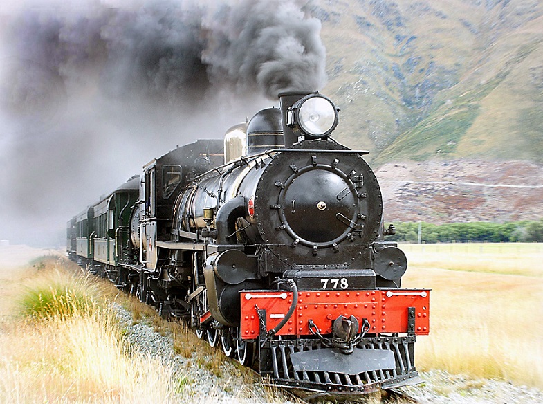
That’s what you will discover in this learning unit. We start with a discussion about different types of motive power. You might remember the big steam engines with with those impressive clouds of smoke and steam, that’s exactly where we start!
Old steam locomotive (photo by Bernard Spragg)
1.4.2 Sources of Motive Power
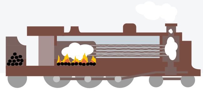
The first trains were driven by steam power. Coal or oil is burned to heat water to steam, this steam is used to drive the engine. Therefore, a steam locomotive is required to carry water and fuel.
Nowadays, almost all running steam locomotives are used on heritage railways or are working on isolated narrow gauge railways. High maintenance costs, low fuel efficiencies and the need for numerous water supply facilities are the reasons that electric and diesel traction are the preferred means of motive power.
Diesel traction is comparable to steam, as a diesel train also carries its own fuel. Instead of a steam engine, a diesel engine is installed.
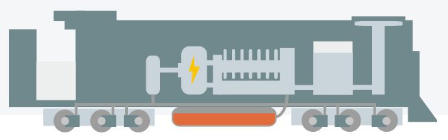
The diesel engines in a diesel locomotive don’t always drive the wheels directly like a diesel engine in an automobile does. Often the diesel engine drives a generator, which produces electricity that is used to drive electric motors on the wheels. These diesel-electric locomotives don’t need a gearbox. Both diesel locomotives and diesel multiple units are in use on railway networks around the world.
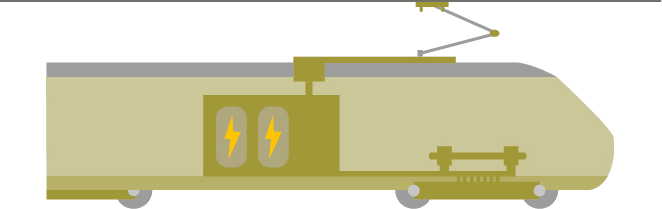 Electric traction forms the alternative for diesel traction. Electric trains are equipped with electric motors only. Electric power is obtained from the infrastructure, either by means of a catenary or a third rail system. On current railway networks, both electric locomotives and electric multiple units are in use.
1.4.3 Getting Power to the Trains
In electrified railway systems a distribution grid transfers the energy from stationary substations to moving trains. Typically, this is achieved by either a rigid conductor rail at ground level or resilient overhead contact line. For high speed lines (above 80 km/h) there is generally chosen for an overhead contact line system. This is due for safety reasons, because above 1000 Vac and 1500 Vdc it is only allowed to use overhead contact line systems.
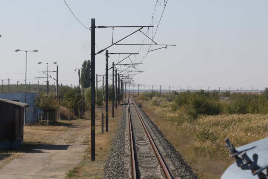
Catenary System
Almost all designs of overhead contact lines in the world, and all designs in the Netherlands, use a secondary wire that supports the mounting of the contact wire and which forms a catenary shape. From which the name catenary stems from. The whole overhead contact line system is commonly referred to as the catenary system. The system consists of a contact wire, which is in contact with the pantograph. To mount this contact wire as smooth and level as possible use is made of a second wire and droppers in between to connect both wires. This allows for that the contact wire is mounted as smooth as possible. The electrical coupling between the contact wire and the train is achieved using a current collector or pantograph. Reliability of the energy transfer system, including catenary and pantograph, is primarily dependent on the quality of the aforementioned coupling. The electrical coupling is achieved by mechanical contact which relies on the dynamical interaction between pantograph and catenary system.
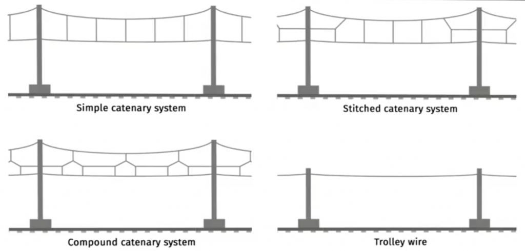 To enhance a stable energy supply the contact force between catenary and pantograph must be constant and steady. This is hindered by stiffness variations, for example at bridges and tunnels but to a lesser extent also when passing supports. Therefore different configurations of catenary suspension systems have been proposed and are being used, but almost all designs can be grouped into four main types. Except the trolley wire that has a single wire, the others have a messenger wire connected to the contact wire by the use of vertical droppers. The reason for this more sophisticated design is to decrease the variations of stiffness along the length. When the speed of the train increases this becomes more important and thus more sophisticated designs are required, as can be seen in the figure below.
Stagger Motion
A lateral stagger motion is applied in all catenary structures in order to evenly wear the contact strips of the pantograph. Differences can be found between the alignment of the messenger and contact wire. They can be mounted parallel to each other, where they both describe a stagger motion or the messenger wire is aligned with the track and only the contact wire follows a stagger motion. In the latter case the wires are in a more horizontal position to each other and hence this system is less prone to lateral deflections due to the wind. The maximum permissible lateral deviation is 0:55m.
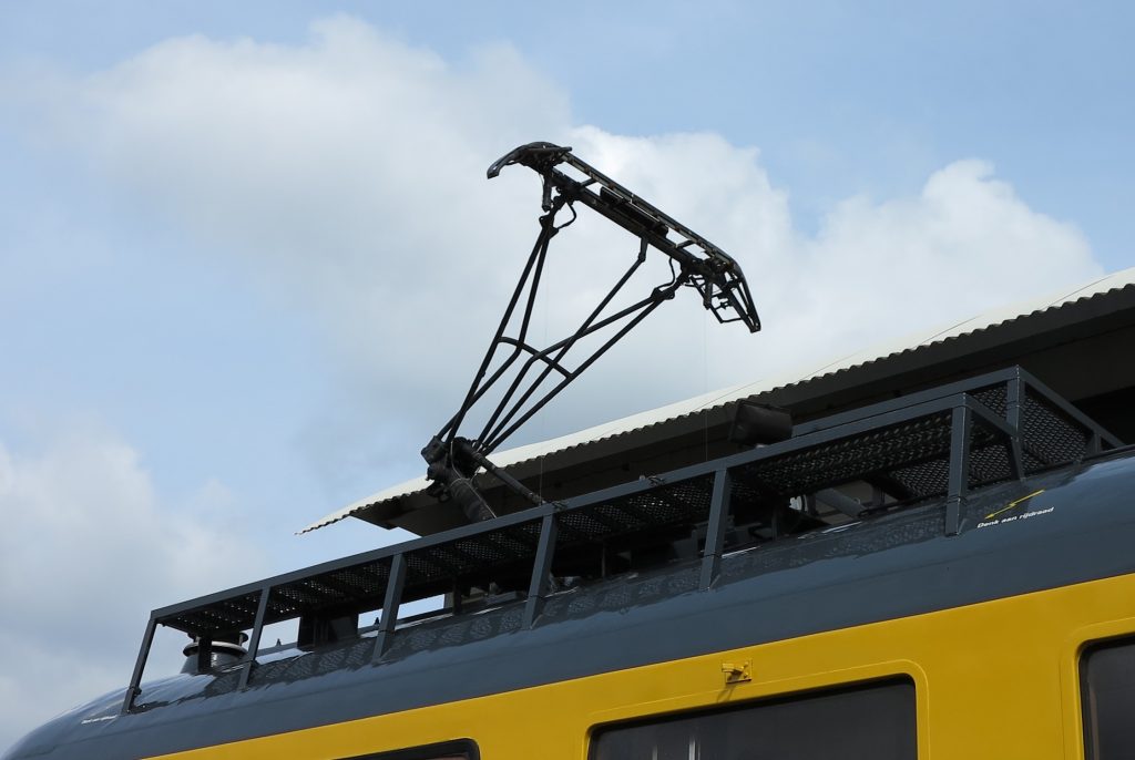
Pantograph
The pantograph is the device on top of the train that extracts the energy from the catenary system. The pantograph is also referred to as current collector. Where the catenary systems is resilient the pantograph as well. The pantograph pushes gently against the catenary and gentle force that is necessary to lift the device is often established by air pressure. As the pantograph just pushes gently it is critical that all parameters of the pantograph fit the catenary system, because a gentle push also means that the two come loose very easily (which we do not want).
Present day pantograph often look like the one in the picture below. It consists of the lifting device based on air pressure, a frame that is responsible the movement of the contact strips is only in the vertical plane. And the contact strips that are sliding along the catenary. Between the contact strips and the frame are some springs to get just the right and adequate gentle push. To compensate for aerodynamic effect winglets (which can cause that the pantograph wants to lift like an aeroplane and starts to push too hard) are used, so they are essentially upside down aerofoils.
You might wonder where the name pantograph comes from and you might know that a pantograph is a device also used to scale drawings. Actually pantograph refers to the mechanism of linkages. In history the first designers of a pantograph (or current collector) for a train used this pantograph mechanism in their design, because this was an easy way to lift the contact strips vertically. Because of that mechanism that was used in the past we started to call the devices on top of the train pantographs. For current day systems the term pantograph is actually a misnomer as the actual pantograph mechanism is not present anymore.
3rd Rail system
Instead of using a resilient overhead line it is also possible to collect energy from the rails, which requires a third rail. Because third rail systems present electric shock hazards close to the ground, high voltages (above 1500 V) are not considered safe. A very high current must therefore be used to transfer adequate power, resulting in high resistive losses, and requiring relatively closely spaced feed points (electrical substations). For these reasons this systems is only used for low-speed, light-rail, systems. The electrified rail threatens electrocution of anyone wandering or falling onto the tracks. This can be avoided by using platform screen doors, or the risk can be reduced by placing the conductor rail on the side of the track away from the platform, when allowed by the station layout. The end ramps of conductor rails (where they are interrupted, or change sides) present a practical limitation on speed due to the mechanical impact of the shoe, and 160 km/h (100 mph) is considered the upper limit of practical third-rail operation.
One might think why a third rail is required to do so as we need two polarities, which only two rails can cover. The first idea for feeding electricity to a train from an external source was by using both rails on which a train runs, whereby each rail is a conductor for each polarity, and is insulated by the sleepers. This method is used by most scale model trains, however it does not work so well for large trains as the sleepers are not good insulators. Furthermore, the electric connection requires insulated wheels or insulated axles, but most insulation materials have poor mechanical properties compared with metals used for this purpose, leading to a less stable train vehicle. Nevertheless, it was sometimes used at the beginning of the development of electric trains.
1.4.4 Pantograph and Catenary Interaction
Traction systems lecture
Sorry but there don't seem to be any downloads..
Subtitles (captions) in other languages than provided can be viewed at YouTube. Select your language in the CC-button of YouTube.
1.4.5 From Power to Traction
Traction is the actual force that a train utilizes to push itself forward on the track. To understand traction you should compare a train to yourself running. What do you need to do to get yourself forward if you want to run? You have to exert force with your feet onto the street. That’s exactly what a train is doing: its wheels exert traction force to the track.
The amount of motive power available determines the amount of traction available. A heavy train requires more traction to move compared to a light rail vehicle. Therefore a heavy rail locomotive disposes more power than a light rail vehicle. But there is more to it. For example, the maximal velocity that a train can attain is also governed by the available power.
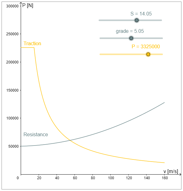
This is understood by the traction curve. The traction curve is a graph that shows the available traction at each velocity. The graph below shows such a curve. Now picture yourself running again, if you run in a crosswind or uphill, you need more motive power. This extra amount of force is known as the resistance force. The same is true for a train. It turns out that this resistive force also depends on the trains velocity. Therefore, also a curve showing the resistive force is shown. If traction force equals resistive forces, the maximal velocity of the train is attained.
In the full course on edX you are able to use this interactive curve so you can see what the effects are of changes in the parameters.
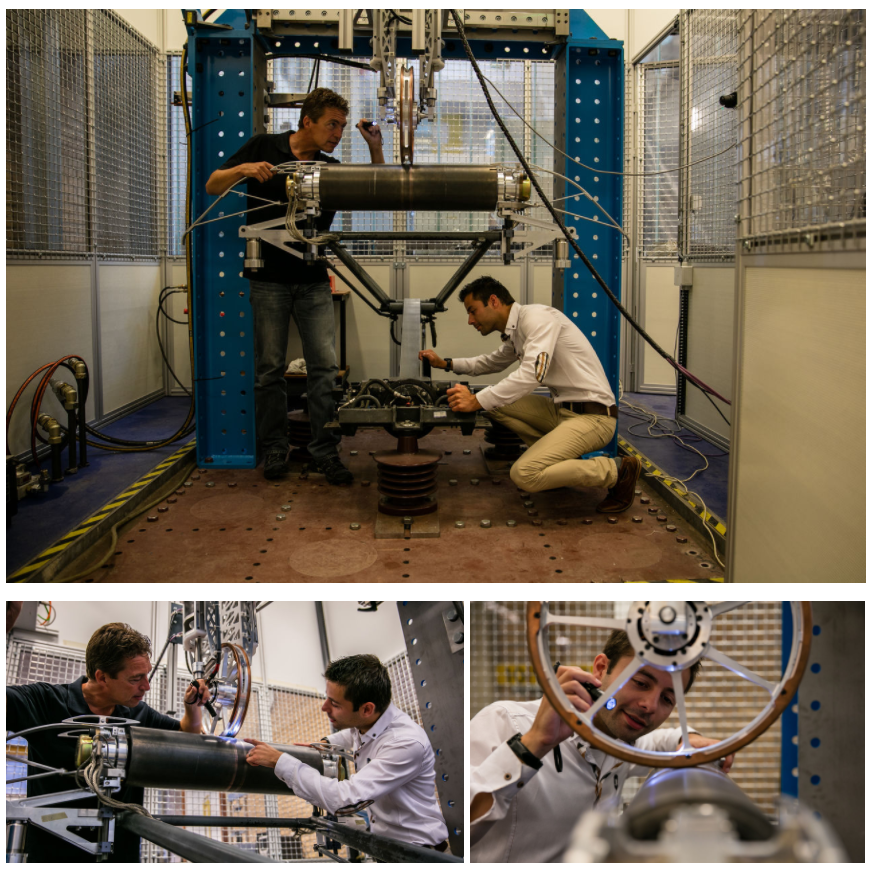
1.4.6 TU Delft Rail Lab
We welcome you to the TU Delft Rail Lab. This is where we can test and innovate on a 1to1 scale and is where the research and computer simulations come to life.
One of the projects currently in development is our rolling pantograph, which is mounted onto our catenary simulator. The simulator enables us to test the interaction with existing and new pantographs to improve the point of contact. We can upload any part of the Dutch electrified network onto the system, after which, it is exactly simulated, giving us extremely detailed insights. The rolling design is created to limit wear of both the wire as well as the pantograph itself. Where a large part of the railway infrastructure is equipped with a catenary system, the pantograph has had a similar design since the very beginning. This test equipment is used by our research team and technical staff to design new models, creating a essential step towards proven technology before using it on actual trains.
 Source: TU Delft Communication CEG / Railway Engineering Group / Frank Auperlé (re-publishing only in consultation: j.q.vandijk@tudelft.nl)
More information on our rolling pantograph and catenary simulator:
>> http://railahead.tudelft.nl/pdeng-defence-of-harm-visser/
>> http://railahead.tudelft.nl/studies/testing-device-concerning-pantograph-catenary-dynamics/

Railway Engineering: An Integral Approach by TU Delft OpenCourseWare is licensed under a Creative Commons Attribution-NonCommercial-ShareAlike 4.0 International License.
Based on a work at https://ocw.tudelft.nl/courses/railway-engineering-integral-approach/.