


5.2.1 to 5.2.4
Course subject(s)
5. Monitoring and Maintenance
Monitoring

5.2.1 What is Monitoring?
Since monitoring is an essential part of condition-based maintenance, it is good to get into more detail about monitoring and how to do it. According to the Oxford dictionary ‘to monitor’ is to ‘observe and check the progress or quality of something over a period of time’. This definition contains two essential parts:
- First of all one needs to be able to judge the quality of the monitored object in a reliable way, which gives similar results when repeated. Although in some cases this can be done by humans (by looking at it), in the vast majority of cases some sort of measurement and data interpretation would be needed.
- The second essential part of the definition is considering the quality of something over a period of time. In other words, a single observation of the quality at a single point in time is not considered monitoring. Monitoring is defined as multiple observations over a period of time in order to obtain a certain degradation.
In general, you can say that with monitoring you try to answer the following questions:
- Is the system damaged?
- Where is the damage located?
- What type of damage is present?
- What is the extent of damage?
- What is the remaining useful life of the structure?
This information is essential if you want to effectively plan maintenance and assure safety of the structure.
5.2.2 Testing Quality
Since an essential part of the definition of monitoring is to test and quantify the quality, knowing how this can be done is important. In general, there are two ways of testing: destructive testing and non-destructive testing.
Destructive testing
In destructive testing, a structure or part of a structure is tested to its limits, in which, as the name of the method suggests, the tested sample is broken and can no longer be re-used. Good examples of destructive testing are the pressure tests on concrete samples (like in the video below). Since destructive testing determines the exact moment and load of failure, this test can really accurately determine the expected strength of the whole structure. But because part of the structure cannot be reused, destructive testing is often not ideal for structures that need to remain in service.
Non-destructive testing
Non-destructive testing is different from destructive testing in the fact that samples will not break and can still be used in the structure after the tests. However, often the samples need to be taken out of the structure and into a laboratory to do the tests, making the structure as a whole temporarily unavailable.
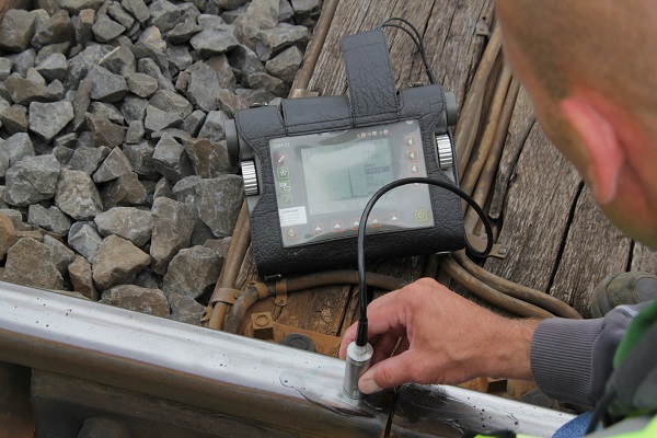
In non-destructive testing, the limits of the sample are found with the help of the known behaviour of the sample and the material it is made from. Consider a steel component for example. By testing just in the range of the elastic deformation, a good indication can be given of the maximum stress before failure. Other methods for non-destructive testing often are performed by sending in a certain signal into the structure and measuring the response. This can be done with vibrations, but many more techniques are available!
Photo of non-destructive testing of a rail joint (copyright TU Delft)
5.2.3 Setting up a Monitoring System
When you want to set up a monitoring system, it is essential to first define what you want to monitor. A monitoring system in general will only work for the processes it is designed for. For example, if you want to monitor the wear of a normal stretch of railway track you would use a very different system than when you want to monitor the quality of an insulated joint. Even though this sounds straightforward, people often still think a single monitoring system can be the solution for all their problems, which is a dangerous assumption!
Once you know the process you want to monitor, you need to define how changes can be measured and what accuracy is needed. This is essential in order to select the right sensor for performing the measurement. When measuring wear for example, which is a slow process, you don’t want to use a normal ruler since it is not accurate enough (by far) to compare multiple measurements. Or when high frequency vibrations are part of the process, a low frequency acceleration sensor will not suffice. All in all, there are many considerations for selecting the right sensor out of the enormous amounts of sensors available. Combined with the sensors and the preferred way of measuring a suitable data-acquisition system needs to be selected.
Even though one can not do monitoring without a suitable measurement system, using a measurement system in itself will not result in monitoring. Whatever sensors are used, all they do is provide data. In order to relate this to the quality, the data needs to be interpreted. For most monitoring solutions, unique models need to be built to do this interpretation. This can be as simple as just single threshold values, but can also include complex mathematics.
5.2.4 False Conclusions
One needs to be aware that there are many possible error sources in the whole data collection and analysis system, which can lead to false conclusions. Setting up a complete and correct system therefore is of the uttermost importance for a good monitoring solution!
The response of a sensor is not always 1 on 1 with the input. There are many factors to take into account which can influence the results.
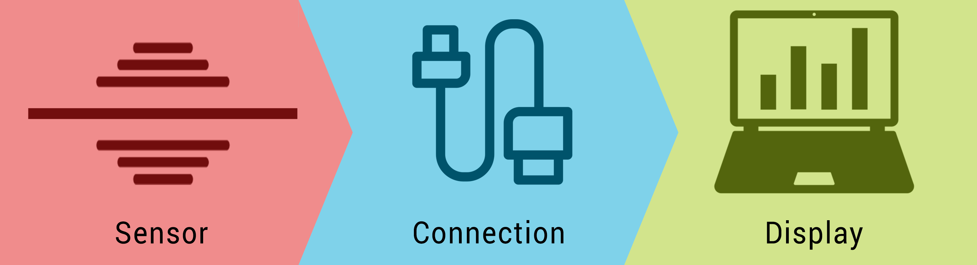
Sensor
- The sensor needs to be mounted on the object that needs to be measured. However the quality of this mounting, which is often done with epoxy, depends on many aspects such as temperature and the type of the epoxy used. This can have a damping effect on the signal.
- The self-dynamics of the housing of the sensor should not be in the range where the signal you want to measure is in. The self-dynamics are the frequency in which the sensor naturally wants to vibrate. When the sensor is excited at this frequency or close to this frequency the accumulated vibration in the housing will make the sensor readings completely useless.
- The binding post (which holds the sensing element) always has some manufacturing tolerances making the sensor have some uncertainty. For example non-perfect outlining of the measuring axis will have influence on the way the sensor responds to an excitation in its measuring axis but also will make it respond to an excitation on a different axis.
- The seismic mass of an acceleration sensor is the most important part of the sensor. However if it is not seated perfectly this will influence the measurement.
Connection
Getting the signal from the sensor to the computer that will do the final analysis also requires multiple steps which all have the risk of introducing errors in the final data:
- The sensor needs to be connected to a cable to allow for the transmission of the data. This connection however may introduce errors. If the contact between the sensor and the wire is not perfect the resistance can influence the actual signal
- Once the signal is in the cable it still can be influenced. First of all if the cable is to long the internal resistance of the cable can become problematic. Another risk is the presence of external magnetic fields around the cable, which will induce an extra signal in the cable itself
- Signal conditioning is often used to filter out unwanted signals from a sensor. However if the set up of a filter is not done correctly the wrong parts of the signal might be filtered out
- To transform the analog signal into data that can be read by a computer a transformation of the data is needed. This transformation however has to take continuous data and transform it into discrete data. If the stepsize chosen for this discrete data is too large an extra uncertainty can be introduced in the data
Display
Even when all the data comes in, in perfect condition there are still problems that can be introduced in it before displaying the data:
- Software errors can cause the data to become corrupted or altogether lost
- Humans are known to make mistakes as well. Since there always is some human interaction in displaying the data, human errors are a risk as well for the system

Railway Engineering: An Integral Approach by TU Delft OpenCourseWare is licensed under a Creative Commons Attribution-NonCommercial-ShareAlike 4.0 International License.
Based on a work at https://ocw.tudelft.nl/courses/railway-engineering-integral-approach/.