


5.3.1 to 5.3.5
Course subject(s)
5. Monitoring and Maintenance
Railway Monitoring Techniques

5.3.1 Track Geometry Measurements 1
Monitoring in railways is not something new. Many techniques are already being used which allow to monitor the railway system (or parts of it). This chapter will discuss some of the techniques that are being used nowadays.
Ultrasonic inspection
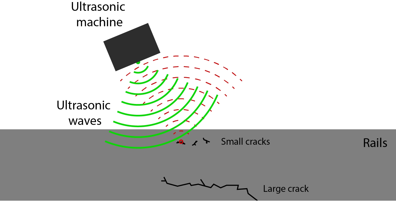
In railways, ultrasonic inspection is used mostly for finding internal cracks within the rail and measuring their size. The principle behind ultrasonic measurements is somewhat comparable to the more commonly known radar and sonar techniques. A signal is sent out into the structure after which the reflection of the signal is captured and analyzed.
Ultrasonic measurements have the advantage that due to the short wavelength that is being used they are sensitive for relatively small cracks in the track. However this also makes that they are relatively sensible to any distortion from the outside, making it important to have the measurement unit close to the rail, preferably with some conductor in-between the sensor and the rail giving direct contact. While doing inspection from a vehicle, this is practically impossible, thus reducing the reliability of the method.
Another problem with ultrasonic inspection can be found in the masking effect caused by, for example, welds or small cracks near the surface of the rail. If a small crack near the surface reflects the ultrasonic signal, a larger crack deeper in the rail might not be found, as is explained in the image below.
Eddy current inspection
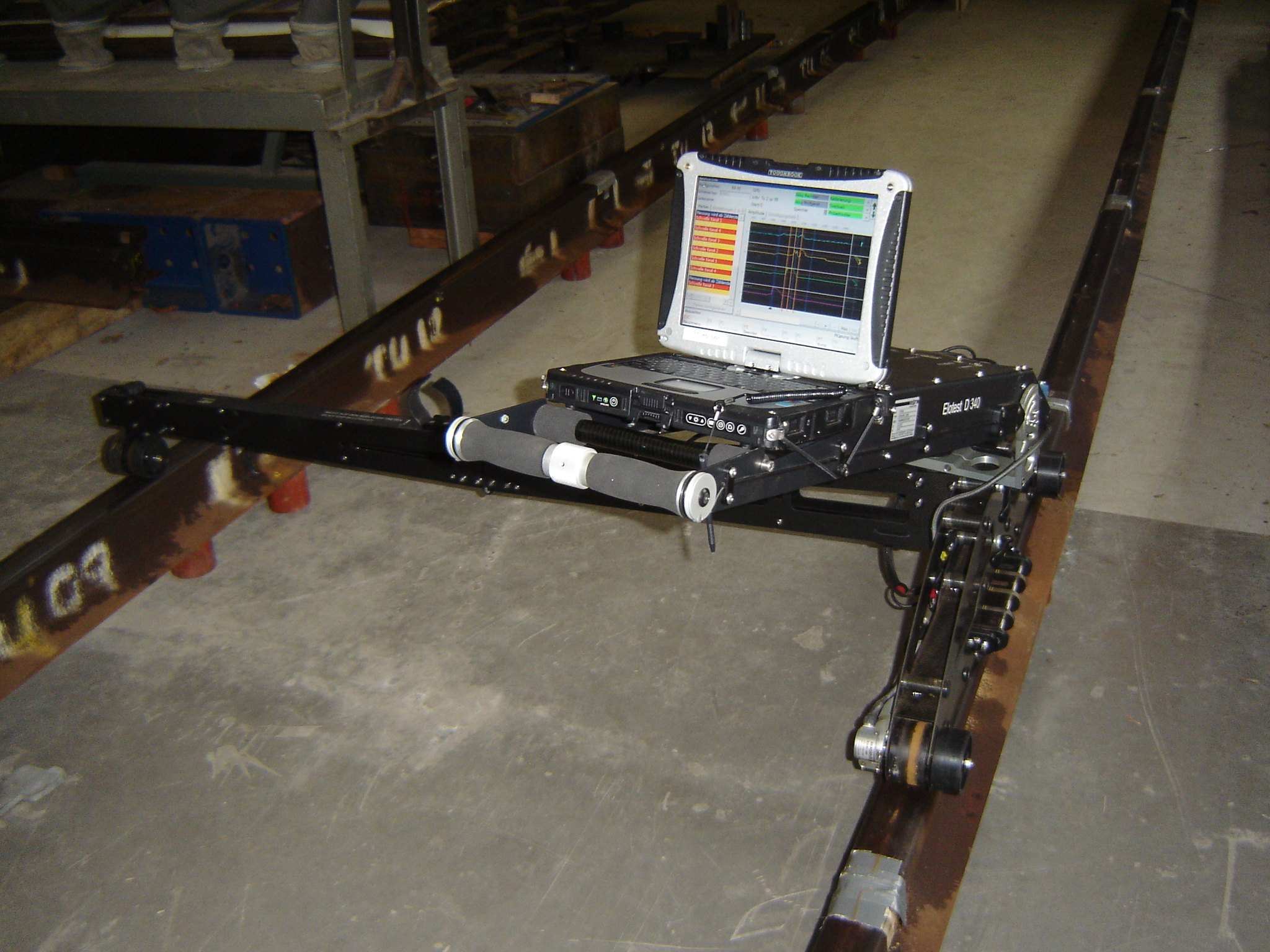
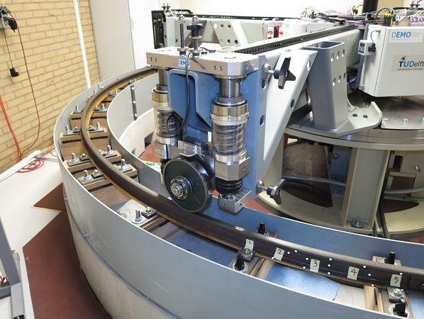
Eddy current inspections can only be used to detect defects in or near the surface of the rails. This technique works by generating loops of currents in the surface of the rail with the help of changing magnetic fields. Within an intact rail, these loops will form smoothly; however, when there is a crack in the rail surface, these eddy currents will be interrupted. A sensor is used to pick up on these currents, and thus determine whether the rail is damaged or not.
Eddy Current inspection rig in a laboratory (Copyright TU Delft)
Train mounted acoustic measurement systems
Acoustic inspection can be used both in contact and non-contact measurements. Acoustic measurements are mostly used in a passive way, thus only having a receiver. This receiver, records the sound which is coming from the wheel rail interaction. When mounted on a train, the measurements are normally non-contact measurements, listening at the sound generated between the rail and the wheel. The level of the noise being generated and the frequency can give information about the roughness of the rail, for example, while local spikes in the sound indicate discontinuities in the rail surface.
5.3.2 Track Geometry Measurements 2
Thermographic inspection
When heating a specific point or section of track, the distribution of this heat can tell a lot about the quality of the rail. Discontinuities in the track will influence the conductivity for heat flow. When following the heat distribution with an infrared camera, these discontinuities in the track can be found. The main advantage of this system is, it can inspect larger lengths of rail at the same time when compared to the other methods. However, there is a tradeoff between the length of rail measured at a single given time and the amount of detail that can be gotten from the measurements.The disadvantage of this system is that a certain heating source is needed, which traditionally were often high powered lamps. Nowadays, the technique is also often combined with eddy-current systems, to induce local heating.
Inspection using visuals
 Visual inspection can be done in two general ways. The ‘old fashioned’ way of simply sending someone in track (in person on foot or in a cart to visually inspect the track), or the more modern way of taking images of the track with a vehicle and analyzing this from behind a computer, as seen below (copyright TU Delft).
Both ways have their advantages and disadvantages. When going in track, you are really dependent on the weather. If there is a lot of sun, reflections might influence the possibility of finding small defects; on the other hand, raindrops can also mask defects. Another problem with in track inspections is safety. In many countries, visual inspections can only be done within a certain distance from the track, while the track is in normal operation. For more detailed inspections, one would have to go in at night, which gives additional problems with lighting.
Using images made from of a moving vehicle solves both of these problems. When watching the recordings on a computer, the visuals are much more constant and allow for close up inspection. However, the disadvantage is that the track can only be viewed from the predefined angles at which the images have been taken during the measurements. It is not possible have a complete view of the rail and its surroundings from all angles.
Laser measurements
Lasers can be used to scan the rail from a running train (usually a monitoring training). This can give information about the shape of the head of the rail, the exact distance between rails, the cant and many other parameters, depending on the system that is used. When combining this with other sensors, such as high-accuracy GPS receivers, it is possible to accurately determine the exact position of the rail and its horizontal profile. The most accurate systems are able to do this with an accuracy of about 1 centimeter. This makes using these combined measurements very useful for finding track subsidence, for example.
5.3.3 State of the Art Techniques
All of the monitoring techniques mentioned below are state-of-the-art. They are the newest innovations researched by universities and companies.
Instrumented crossings
Vibration-based condition monitoring is a technique which estimates the state of a component of interest by measuring its dynamic response. One of the benefits of this technique is that it is non-destructive. This technique can be used for cases where a known excitation is applied (for instance with a calibrated impact hammer), but it is also very applicable to situations where the input is not known. In this case, the technique is also non-intrusive, because the responses are obtained during normal operation.
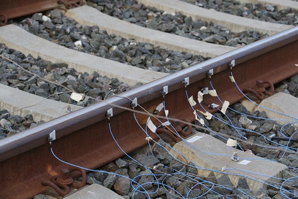
This technique is therefore very suitable to monitor railway components, like crossings or insulated joints. These are impacted by every axle that runs over it, which creates high peak loads, but also results in a large dynamic response, which contains information about its state. Measuring these vibrations is done by attaching accelerometers to the components of interest.
When sufficient data is acquired, the measured response of each axle can be compared to a known response of the healthy condition and the state can be determined. By analyzing the higher frequency content of the signal, anomalies like surface defects can be detected. The content with lower frequencies typically contains information about the support condition of the rail components (like ballast voids) or structural defects (like loose bolts).
TUDelft patented ABA
 The patented ABA system from TUDelft uses axle box acceleration measurements to find different problems in the track. With this measurement acceleration sensors are mounted on the axle boxes of a train. While driving at normal operating speeds, these sensors feel any excitation of the wheel due to disruptions in the rail. When analyzing the signals, both long range defects, such as temporal changes in the running band, and short range defects, such as cracks in the rail, can be found. These measurements have proven to give an accurate representation of the severity of defects. More developments currently are working on accurately predicting growth rate, thus allowing for better maintenance planning.
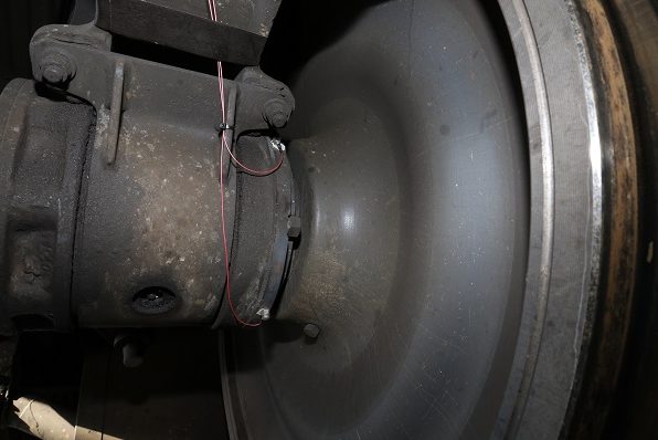
Photo of the ABA system sensors (Copyright TU Delft)
Video Gauge
With a video gauge measurement, it is possible to accurately track the movement of the rail at multiple locations simultaneously while a train is passing over. The system consists of a high speed camera with special software, which can track special targets. Using this system, it is possible to monitor transition zones or insulated joints, for example.
Currently this system is only being used for research purposes, due to pricing and the fact it needs an operator.
In the video below you see the video gauge measurement in action. A train is passing while the video gauge is scanning the targets and thus measuring displacement. The results are then displayed in matlab showing the vertical movement of the track during this passage.
5.3.4 Substructure and Vehicle Measurements
Vibration measurements
 Vibration measurements can be used to determine the spring constants (k-value) of the substructure. In order to do so, a vibration is generated, either on board of a measurement vehicle or on the rail directly. By measuring the response of the rail, the spring constants can be determined. These spring constants are essential for a good distribution of the load and keeping the track stable. An example of a vehicle capable of doing these measurements can be seen in the picture below.
Radar measurements
Ground penetrating radar measurements can be used to determine the quality of the ballast, sub-ballast and sub-grade. Radio waves are send into the ground after which reflections are received. The reflections can be used to determine the quality of the different layers of the substructure.
Rail mounted Acoustic Inspection Techniques
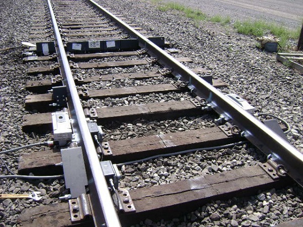
 The rail mounted acoustic inspection techniques are based on the same principle as the train mounted techniques. However, due to mounting them on the rail, they can be used to inspect the passing vehicles. This can, for example, be used to find wheel flats or bearing problems. With just a few rail mounted acoustic inspection locations mounted at strategic locations, it is possible to monitor the quality of a whole fleet of trains.
Photo of sensors mounted on the rail (Copyright TU Delft)
Hot box detector
 One of the parts of a train which causes common failures is the axle bearing. When failure happens, the friction inside increases dramatically, which causes the axle box to heat up and become a so-called ‘hot box’. Detectors placed at strategic locations next to the rail are used to spot these hot boxes and give out warnings by reading the heat of the passing axle boxes. The disadvantage of this system is that the damage has to be severe for the axle box to heat up significantly, leaving only a short time frame before complete failure, which can cause fire or, in the worst case, a derailment.
Photo of a Hot Box Detector (Source)
5.3.5 Research Tools TU Delft
Research tools
In order to perform research into the behaviour of the systems research tools are needed. Of course computer models are really important in this, however modelling is never a perfect representation of reality and can always have some errors (no matter how small). For this reason more research tools are available at the TUDelft.
Pantograph-Catenary measurement set-up
This test set up is specifically designed to simulate all the interaction between pantograph and catenary. Any type of pantograph can be installed in this set-up, after which detailed research can be done looking at the behaviour of the total system. Stagger motion, vertical displacement and even hard points in the catenary can be simulated in this set-up. In all these situations contact forces can be measured, but also the amount of contact-loss between pantograph and catenary can be monitored. Using this set-up better research can be done to optimize the system and thereby decrease the chance of failures. Also new types of pantographs can be tested in this set-up. The set-up is a hardware in the loop type of set-up, in which actual feedback from the hardware determines the behaviour of the response. This is necessary since the pantograph-catenary system has a high amount of interaction, making the behaviour of the catenary highly dependent on the behaviour of the pantograph.
In the video the catenary interaction model is seen with our rolling pantograph design. Sometimes the contact is briefly interrupted by the movement of both, which also happens is real life situations. The test setup can simulate actual parts of track to analyse the behaviour of the pantograph. More on the rolling pantograph in the next section.
Wheel-rail interface measurement set-up
The wheel-rail interface measurement set-up at the TUDelft consists of 4 arms, moving over a round track with a diameter of around 4 meters. The wheels and rails in this set-up are on a scale of 1 to 7.
The loads have been scaled in order to create the same stresses within the wheel-rail contact, as compared to the normal situation. The unique part of this test set-up is the ability to also simulate traction forces or breaking forces on the rail. This is achieved by the wheels having a separate drive engine, allowing to put in a certain speed difference, creating the corresponding slip in the system. The maximum operating speed of the set-up is 40 km/hour during which the arms experience high centrifugal forces. Each wheel will go around one time per second, creating a high number of total wheel passages over time on the track. When running the set-up over longer periods of time this is ideal for simulating and monitoring the growth of defects on the rail (which normally can take years), gaining more knowledge about their origins and behaviour. This can also be used to make better predictions of the remaining useful life of a defect once it has been found in the track.
CTO measurement vehicle
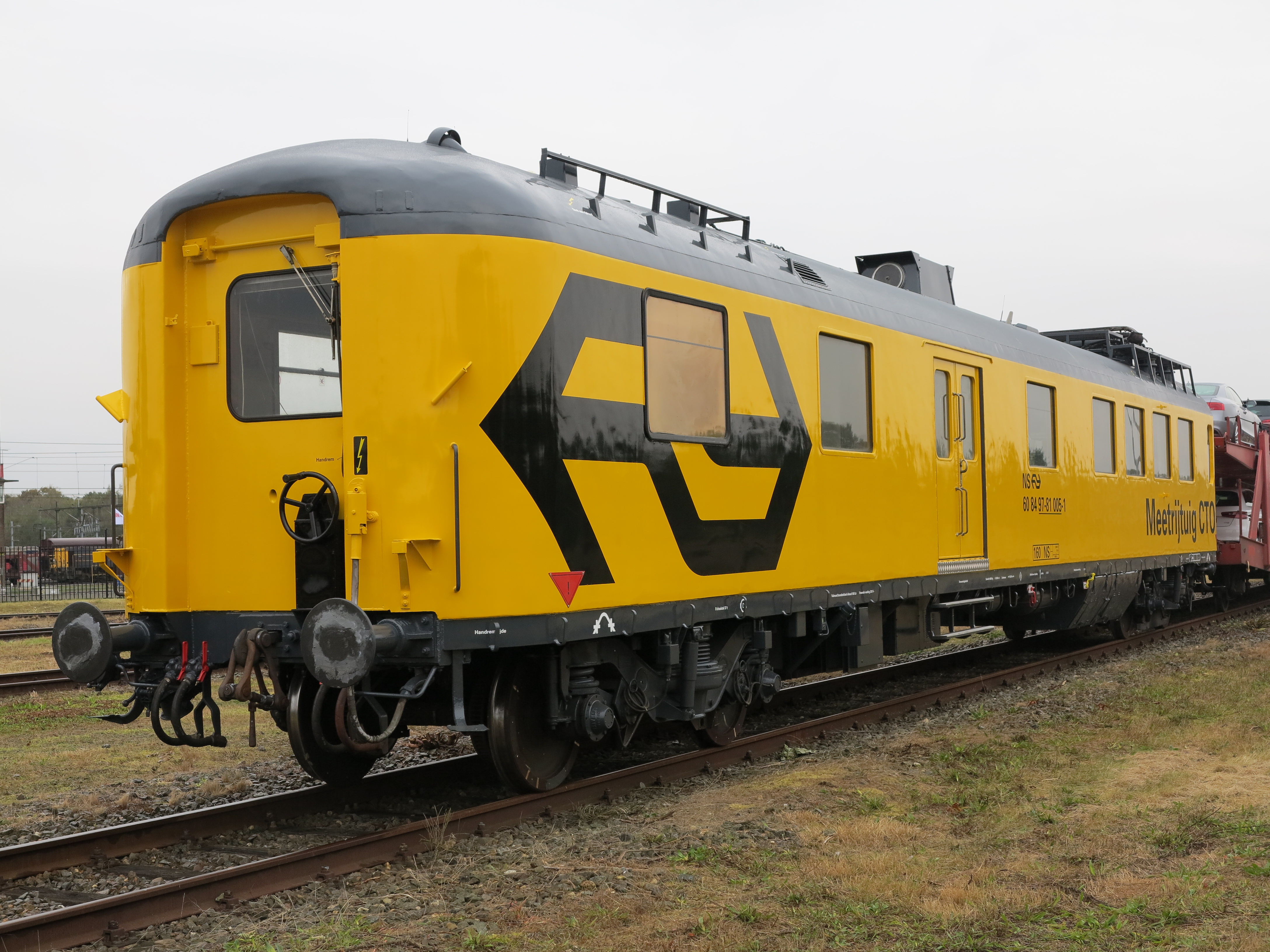
For general usage positioning data is available, both from a highly accurate GPS system and a 1000 pulse per revolution tacho system. By integrating this data with data from a 3d acceleration sensor on the body, the exact position of the vehicle can be known at all-times. This can easily be overlayed with the railway maps provided by ProRail, allowing for precise positioning of measurements and doing validations of the results in the field. For synchronisation of different measurement systems, a ntp-server is available on board of the vehicle.
The vehicle is also equiped with a special measurement pantograph. This allows for testing systems to monitor pantograph behaviour. While driving, this pantograph can also be visually monitored from a dome on top of the vehicle.
Integration
Even though all systems by itself can be useful for doing research, the integration of multiple steps will allow for getting a complete picture. By having lots of knowledge about simulation software, dedicated lab-equipment and our own measurement vehicle, the TUDelft can do all the steps of research. When developing new measurement methods for example, there is a lot of feedback between results from tests performed on the measurement train, computer models of the system and the test-rigs in the laboratory, allowing for the most optimal results.
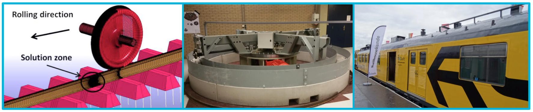
Image showing simulation software, the wheel/rail test rig in the laboratorium and TU Delft measurement train.(All photo’s copyright by TU Delft)
In the video above a crack in the rail has been made in the wheel-rail test rig, to monitor the growth of defects and compare this to the available models and real-life situation.

Railway Engineering: An Integral Approach by TU Delft OpenCourseWare is licensed under a Creative Commons Attribution-NonCommercial-ShareAlike 4.0 International License.
Based on a work at https://ocw.tudelft.nl/courses/railway-engineering-integral-approach/.