


5.3.2 Electrical Engine in the Loop
Course subject(s)
Module 5: Recycle
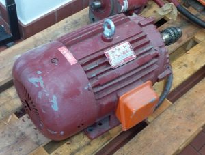
Now we will present you a product which was built some years ago. It is a big electronic engine to convert electrical energy into mechanical energy.
The components are simple enough to show that changes have an effect. It will be slightly more technical that some examples before but do not be afraid we try to break it down so everybody can take his very own massage from this text.
After presenting the engine and its components we will compare a linear and a circular approach. There will be a lot of information we will focus on the energy for the material, manufacturing, transport and disposal. Feel free to look into the other given information as well. But now, the engine:
It is an old electric engine with around 5.5 kW and a weight of around 115 kg.
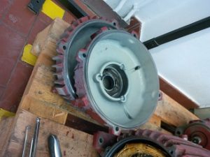
The housing
Let us talk about the housing, which is made out of aluminum. There are three parts. The housing and one housing cover for each side. The weight of those parts are 50.5 kg. All the parts outside are connected with screws. So it is possible to open and close the engine and detach other components multiply time without damaging anything. The internal parts are manufactured with high precision so they are press fit connection. With some force it is possible to disconnect the ball bearings and the magnetic coil from the housing without destroying each of the parts. This means in general it is possible to reuse the housing if you want to.
Covers
There is a simple steel cover, which weights 2.5 kg, to protect the user from the rotating fan . It is one of the outer parts of the housing that is connected with simple screws. The second cover is for protecting the electronic connections of the engine. It is also made out of steel and has a weight of 0.355 kg
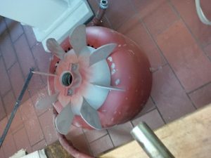
The fan
The fan is made out of 0.325 kg plastic and it is cramped with two screws onto the rotor shaft, it will provide an air current for cooling purpose when operating the engine.
Now you will learn about all the electric parts the engine need to work. You do not have to know each detail or all the electro-magnetic things that happen. The material inside is necessary to work as an engine. Those are mostly cupper and special magnetic steel sheets connected to coils. One static and one which is rotating on the rot mentioned before. With electric energy and magnetism the rod will start to rotate.
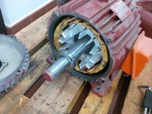
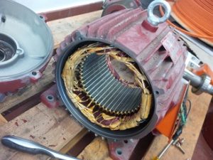
The static coil, the stator
It is made out of copper and special magnetic steel sheets. On the picture you can identify it between the housing and the inner rod. The copper weights 3.84 kg and the steel will add 26.16 kg to the total weight of 30 kg.
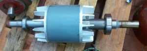
The rotating part, the armature
Copper, steel sheets, a steel rot and two aluminum fans are the parts the armature is made of. We will assume 2 kg of copper, 22 kg of steel sheets, 1kg aluminum and 7 kg for the rod. Therefor the armature has a weight of 33 kg.
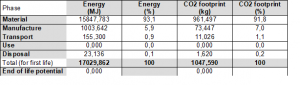
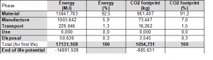
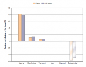
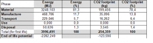
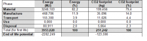
To get an overview about the Materials look at the table below:
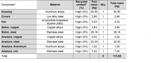
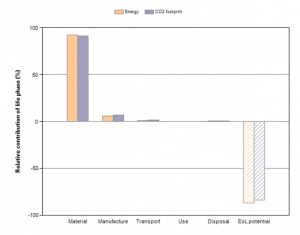
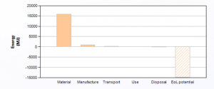
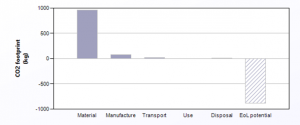
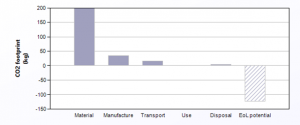
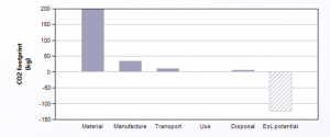
We use a program to calculate the energy consumption and the CO2 emission. Therefor we can set the amount of “Recycled content” as you can see right now, everything is made out of entirely new materials. We used a more vague description of the material so it is easier to cluster the materials for the analysis. The first analysis included the energy consumption from using the engine. We assumed 20 years, 100 days per year, 8h per day with 5.5 kW of energy consumption. The energy consumption compared to the others is huge and made the diagram meaningless. Therefor we exclude the using phase. On the diagram below you can see what the different energy levels for an engine which is built entirely out of new materials and ends up in a landfill.
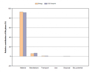
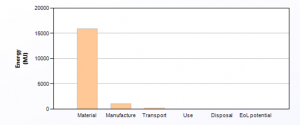
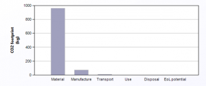
There is also no potential at the end of life due to the fact that everything will end up in a landfill.
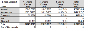
We will now present you a scenario in which this engine needed three times to compare different approaches. The first approach is very easy. The engine is produced and disposed three times as you see in the tables and diagrams above. The total energy consumption will be multiplied by three. This sure is the worst case. It is very likely this does not happen this way even in a very linear economy. Nevertheless let us compare this worst case with one circular approach.
To be fair we will start with a very similar setup as the one before. Everything is made out of virgin materials because it has to start somewhere from the beginning. At the EoL of the product the housing and its covers will be reused as they are, also the fan and the rod of the armature the other steel, copper and aluminum will be recycled. This will not change many for the material itself for the first step, but the EoL potential will rise tremendously.
Now we can assume that the reuse parts are used in the production of the next engine. Also the recycled materials will be no longer entirely new, the typical recycling percentage will be used for the next calculation. The engine will build with the factors mentioned above and reused and recycled as before. This will have again a tremendous impact. This time in the material consumption. Therefor the EoL potential will shrink accordingly because the engine does not longer contain as much energy as before.

For the last life of the engine we assume the same parameters for the input, but at the EoL all materials will be recycled, except for the Fan. This material will unfortunately downcycled.
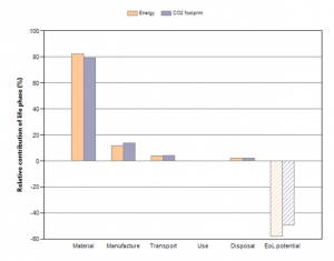
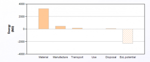
A lot of tables and numbers. Let us compare the necessary energy for the two approaches directly.
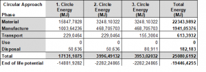
There is a higher consumption for the circular approach for the transport and disposal. For the transportation we had to consider the “way back” for the materials. But what about the disposal? Well, recycling of Aluminum and Steel is does indeed consume more energy than putting it somewhere.
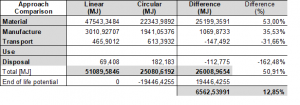
But as you can see this minor investments are worth it overall. The energy consumption is over 50% smaller for the circular approach. Not to mention that there are no perfectly fine materials somewhere on a landfill. By considering the End of life potential in the circular approach you have a consumption of only 12,85% of the energy from the linear approach and except of the Fan all materials within the same loops. By replacing fan material with metal you could manage to keep everything in the loops.
I think this small example can show you how a well-planned product life can change the whole environment. We leave it up to you how much money you could safe only cause by the energy, or how much cups of coffee you could have heat, how many charges for your mobile phone you have left…

Engineering Design for Circular Economy by TU Delft OpenCourseWare is licensed under a Creative Commons Attribution-NonCommercial-ShareAlike 4.0 International License.
Based on a work at https://online-learning.tudelft.nl/courses/engineering-design-circular-economy/.