


6.2.3 The Top-Down Approach: Distributed Ecosystems in Science, Engineering, and Business
Course subject(s)
6: Distributed Ecosystems: Putting It All Together
We introduce in this section a reference architecture for grid computing, which has been deployed widely to support scientific and engineering computing.
Grip Computing: A Reference Architecture
History: At the beginning of the 21st century, advances in networking, computation, and storage made it possible to construct and interconnect very large computers, structured as modern data centers. This remarkable computing power needed good software abstractions so that developers could leverage the infrastructure. Already, scientists envisioned the massive, global- or at least national-scale infrastructure, for example, what would become the WLCG used primarily by CERN physicists and the USA-based TeraGrid supporting cross-disciplinary sciences. What should be the programming model? What should the system architecture be?
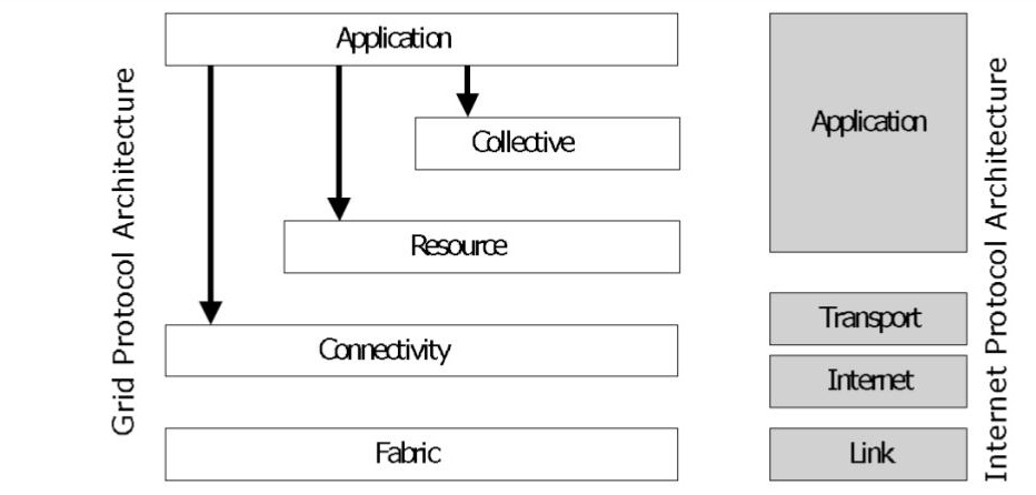
Figure 1. The grid reference architecture. (Source: [1].)
Conceived in the late 1990s, the reference architecture of grid computing represents one of the great conceptual achievements of computer science. Focusing on the most important challenges of its time, it proposes a five-layer architecture. Starting from the bottom layer, which is the closest to physical resources, the layers are:
- Fabric, which provides interfaces to local control. Resources at this level are distributed: for computation, clusters and aggregated individual nodes; for communication: networks, and aggregations of individual links; for I/O: file systems, and aggregations of individual disks; for data management: catalogs and relational DBs; for sensing: sensor networks. This layer includes resource-specific operations needed for sharing resources. It does not include: internal or local protocols to manage distributed resources, e.g., NFS.
- Connectivity, which provides easy-to-use, secure communication. Services in this layer include: a Single Sign-On for the entire distributed ecosystem, the delegation of access rights, and trust management. This layer includes: operations for managed, controlled, secure communication, e.g., GSI; management for naming, e.g., LDAP. It does not include: existing communication protocols, e.g., TLS.
- Resource, which focuses on services for sharing single resources (but possibly large-scale and distributed). It includes: sharing-oriented information and resource management protocols. It does not include: existing data-transfer protocols, e.g., FTP.
- Collective, which enables multi-resource coordination. Typical services include: for naming and location, distributed directory and discovery services; for scheduling, distributed workload management through scheduling, brokering, and specialized operational techniques, e.g., co-allocation, offloading; for fault-tolerance, distributed monitoring, diagnostic, and recovery services; for consistency and replication, data replication and sharing for an entire community, e.g., storage for a Virtual Organization (VO). This layer includes: platforms to develop complex applications that require collectives, such as AppLeS, Condor-G, Ninf, NetSolve, etc. These platforms can be very flexible, so there is no technical limit to what the layer can include.
- Application provides mostly programming models, languages, and frameworks that use lower-layer services through an easy-to-use interface. This layer includes: API-driven distributed systems capabilities, e.g., CORBA, CCA, Cactus, etc.; workflow systems, e.g., Pegasus.
An example from particle physics:
Working toward developing particle physics applications, designers have to first refine the low-resolution reference architecture from Figure 1, then define how a well-understood particle physics application can leverage the refined reference architecture. These are typical steps in top-down approaches, where the lower-resolution reference architectures are increasingly refined toward practical use.
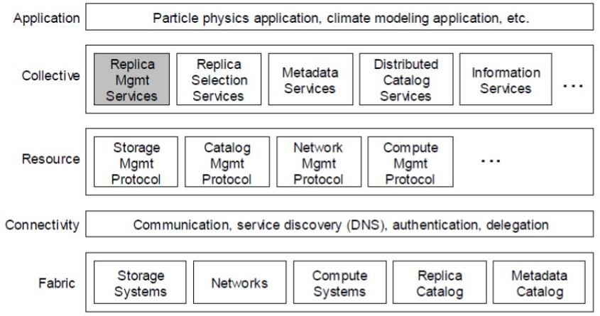
Figure 2. A more detailed reference architecture, derived from the lower-detailed grid reference architecture. This more refined reference architecture is the basis of many particle physics applications. (Source: [2].)
Figure 2 captures the result of the refinement process. The more detailed reference architecture builds on how scientists already do their work. The highlighted component represents the most important contribution of the refinement, which addresses how scientific communities already replicate data, for both scientific and computing reasons. Thus, a replica management service needs to be added in the Collective layer, to manage and in particular locate the many existing replicas of the same dataset.
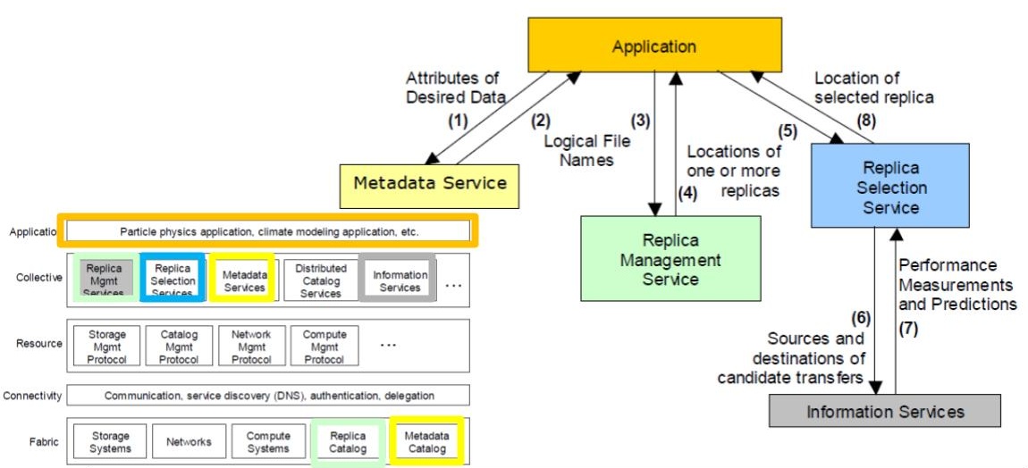
Figure 3. The execution of a particle physics application built in the more detailed reference architecture. (Source: [2].)
Later, the designers, which can be members of the team that produced the architecture in Figure 2, but are likely unrelated local experts, focus on the application. They try to leverage the available services in the reference architecture, so the applications can mostly focus on issues from physics.
The design considers what the applications (A) does, scenario by scenario. In the scenario Figure 3 depicts, A needs to read some dataset. However, it does yet not know which dataset or where it is located. So, (1) A calls upon a Metadata Service (MS, a component in Collective), to which it sends the attributes that define the data. (You can imagine a kind of Google Search here – some searches are very precise, and others loosely describe what datasets are needed; this depends on the scenario). Then, (2) MS searches for the data, using all the local Metadata Catalogs (in Fabric), and finds the logical file names corresponding to the dataset. Assuming this process succeeds, that is, MS returns a non-empty set of results, (3) A asks the Replica Management Service (in Collective) to locate the actual (physical) files and (4) A gets a reply. Then, (5) A contacts a Replica Selection Service (RSS, in Collective), which in turn (6) queries the Information Services (IS, in Collective) it has access to, and (7) RSS gets from IS performance measurements and predictions. Then, (8) RSS selects a good replica for the application, based on the performance data received from the IS component.
Finally, A has access to one file, with good performance (and other non-functionals) if exist multiple replicas of the file. To do this, the application developer did contact only services from the Collective layer, which, in turn, accessed services from the layers below. A very complex operation, possibly involving hundreds of services, was completed with the relatively simple process we just described.
References:
[1] Ian T. Foster, Carl Kesselman, Steven Tuecke: The Anatomy of the Grid: Enabling Scalable Virtual Organizations. IJHPCA 15(3): 200-222 (2001)
[2] B. Allcock, J. Bester, J. Bresnahan, A. L. Chervenak, I. Foster, C. Kesselman, S. Meder, V. Nefedova, D. Quesnal, S. Tuecke (2002) Data Management and Transfer in High Performance Computational Grid Environments. Parallel Computing Journal 28 (5).
Operational problems with the grid reference architecture, from a contemporary perspective: Hindsight is always 20/20, so looking back to grid reference architecture we can identify problems from a contemporary perspective. Such problems were not the main focus of design activity at the time, because other issues, appearing in the lower layers, needed to be settled first. Nevertheless, let’s try this as an exercise. One caveat to the grid reference architecture is that even relatively simple operations, such as accessing replicated datasets, require defining protocols with many steps.
Once the services present in Figure 3 stabilized, and especially the layers Fabric, Connectivity, and Resource matured, it became relatively easy for application developers to bypass the Collective layer. Instead, they created services more suitable for their applications; this is typical of smaller teams using the bottom-up approach. As these services succeeded, they were increasingly considered by top-down designers, and the Collective layer got replaced by a focus on back-end and front-end services between the Resource and the Application layers in the grid reference architecture.
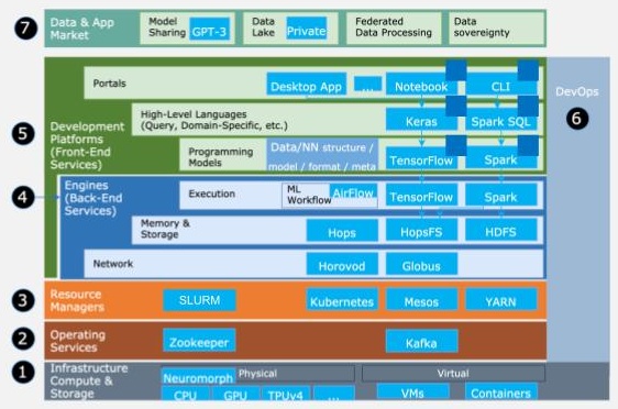
Figure 1. A reference architecture for data center applications. The application domain is machine learning. The application follows a workflow model. (Adapted from [1].)
Figure 1 illustrates the current conceptual battleground, with a reference architecture for data centers. (As discussed in the video clip on reference architectures, this architecture works for many classes of data center applications, from machine learning to graph processing, from online gaming to business-critical workloads.) The figure reflects today’s emphasis on finding architectural solutions for back-end and front-end services, which are over-represented in this architecture. The layers below, from Infrastructure to Resource Managers, are currently well-understood and deliver mature service, but advances in hardware (e.g., new compute and storage architectures, neuromorphic and quantum computing, and virtualization techniques) could renew interest in these layers, starting from Layer 1.
Figure 1 also includes the application, as dark blue squares. The application is easy to miss, showcasing how small it is in terms of development time and software footprint, compared to the other services the distributed ecosystem provides to help the application run well. The application itself is a workflow, consisting of tasks such as filtering the input dataset, which is done using a Spark pipeline, and the machine learning training process, which is done in TensorFlow using the result of the other task as input.
References:
[1] Sherif Sakr, Angela Bonifati, Hannes Voigt, Alexandru Iosup, Khaled Ammar, Renzo Angles, Walid G. Aref, Marcelo Arenas, Maciej Besta, Peter A. Boncz, Khuzaima Daudjee, Emanuele Della Valle, Stefania Dumbrava, Olaf Hartig, Bernhard Haslhofer, Tim Hegeman, Jan Hidders, Katja Hose, Adriana Iamnitchi, Vasiliki Kalavri, Hugo Kapp, Wim Martens, M. Tamer Özsu, Eric Peukert, Stefan Plantikow, Mohamed Ragab, Matei Ripeanu, Semih Salihoglu, Christian Schulz, Petra Selmer, Juan F. Sequeda, Joshua Shinavier, Gábor Szárnyas, Riccardo Tommasini, Antonino Tumeo, Alexandru Uta, Ana Lucia Varbanescu, Hsiang-Yun Wu, Nikolay Yakovets, Da Yan, Eiko Yoneki (2021) The future is big graphs: a community view on graph processing systems. Commun. ACM 64(9).

Modern Distributed Systems by TU Delft OpenCourseWare is licensed under a Creative Commons Attribution-NonCommercial-ShareAlike 4.0 International License.
Based on a work at https://online-learning.tudelft.nl/courses/modern-distributed-systems/