


2.2.3 Comparing the MARCH exoskeletons
Course subject(s)
Module 2. The Building Blocks of the Exoskeleton
In 2015, a team of enthusiastic students thought it would be a great idea to develop an exoskeleton for people with Spinal Cord Injuries. They were inspired by the Mindwalker exoskeleton and thought they could contribute to the developments in the exoskeleton field. And so, the first Project MARCH team was born. The Mindwalker was an exoskeleton that was still in development which aimed for a brain-controlled movement. With this exoskeleton as inspiration, they started their own design. Since then, the frame has evolved a lot over the years. Every Project MARCH team had their own goals concerning the frame concept, resulting in new designs every year.
The first MARCH team had a few key insights concerning the frame design. First of all, they chose to design the frame so that it could be adjusted to the size of the pilot. They also envisioned that the exoskeleton would be small and lightweight, but still resistant to the large torsion forces on the bones. They chose to use aluminium hollow square tubes with extendible connection pieces in the middle. However, it turned out that the connection pieces compromised too much of the strength and rigidity of the bones. Luckily, by that time they found a pilot that was willing to work with them and test their exoskeleton. It enabled them to use non-extendible bones matching the size of the pilot, which increased the rigidity of the frame.
Figure: The frame of the first Project MARCH exoskeleton with bone adjustability
Safety was also an important aspect of their design choices. They wanted the exoskeleton to have a controlled failure mechanism in case of an unintended worst-case scenario. For example, they created a hip bone that would bend in a predetermined direction on impact, without harming the pilot.
In the end, it required quite some iterations for the frame to be able to resist all forces on the exoskeleton. Unfortunately, it couldn’t be done without some compromises on the simplicity of the design though. Although the final exoskeleton design did not turn out to be an overwhelming success, this frame design taught the following years a lot of the trade-offs to be made.
The next MARCH exoskeleton, created by the second team, contained a fundamentally different frame. They still aimed for some sort of adjustability in the bones, but since they knew who their pilot would be very early in the design process they could narrow it down to an adjustability of only a few centimetres or millimetres. With a commercially available exoskeleton – the ReWalk – as a source of inspiration, they still used aluminium as core material but chose a flat design instead of a tubular frame. Using different hole and bolt configurations, different connection heights were possible without having to adjust the length of the bones.
The frame did not only fulfil the function of a weight bearing system, but it adopted multiple exoskeleton functions. For example, it could accommodate the placement of electrical components. It basically became a part of the exoskeleton that held everything together and connected more parts than it could before.
This frame luckily did not have any issues with rigidity and actually was a bit over-designed (it could endure more forces than actually needed). On the other hand, it was quite heavy and since the shapes of the bones were very complex it resulted in a complicated manufacturing process. Especially compared to the first frame, which consisted of very minimalistic parts.
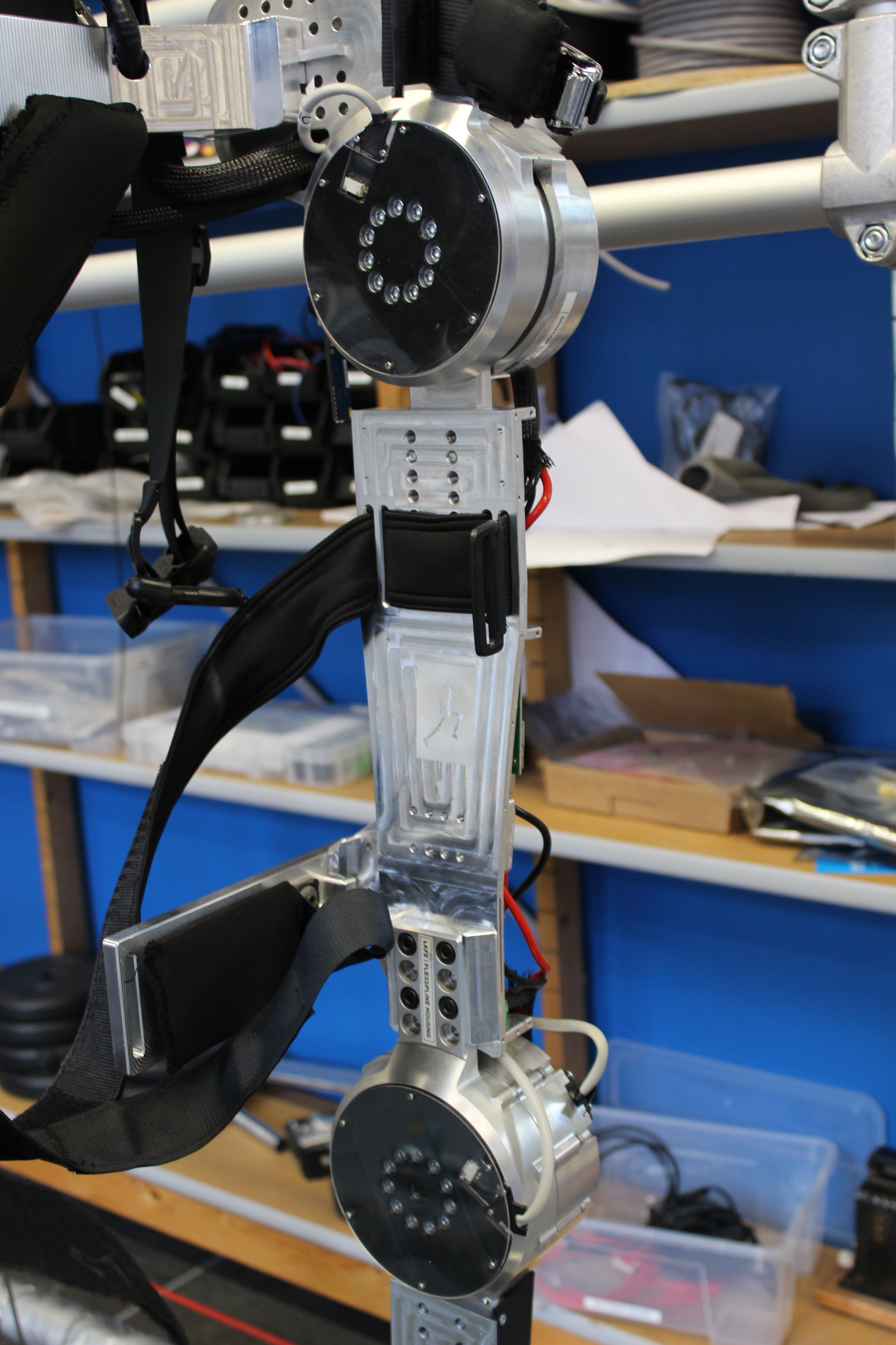
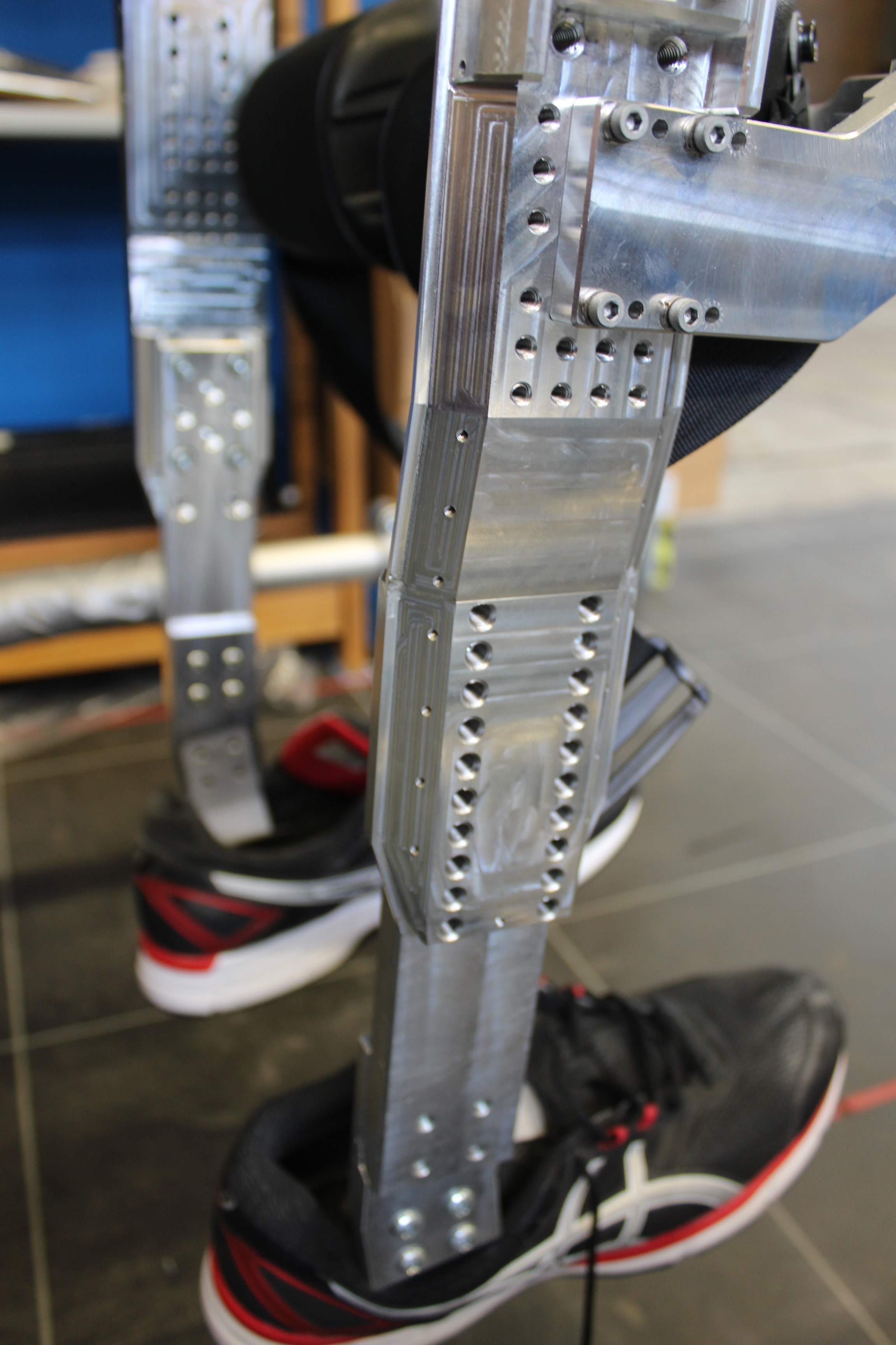
Figure: Frame of the second MARCH exoskeleton
For the third year of Project MARCH, the team found a different pilot. This pilot was about 40 cm shorter compared to the pilot they had the year before. And that makes things both more and less complicated. For the frame as a weight bearing system, it gets a bit easier since the bones can be a bit shorter and the frame has to carry less weight. On the other hand, it also offers less space for the placement of electrical components. The bones were still designed to be multifunctional just like the year before, but they had to add an additional system for the placement of electronics.
The bones were still made of aluminium since they met all the requirements and aluminium isn’t very expensive. Although creating a lightweight exoskeleton was continuously on their mind, safety always came first and is a top requirement. Aluminium also has the benefit of being quite easy to manipulate and therefore is very suitable for manufacturing quite complicated shapes. As you can see, there are quite a few curves, ridges and holes in these bones that need to be in precisely the right spot!
Similar to the year before, this exoskeleton only had a few centimetres of adjustability. It was custom made for the pilot, but since a measuring error is easily made you always want to be able to slightly adjust the frame size. The frame of the exoskeleton was designed to fit the pilot as tightly as possible. By keeping the frame close to the body, it enabled the pilot to have more control over the exoskeleton.
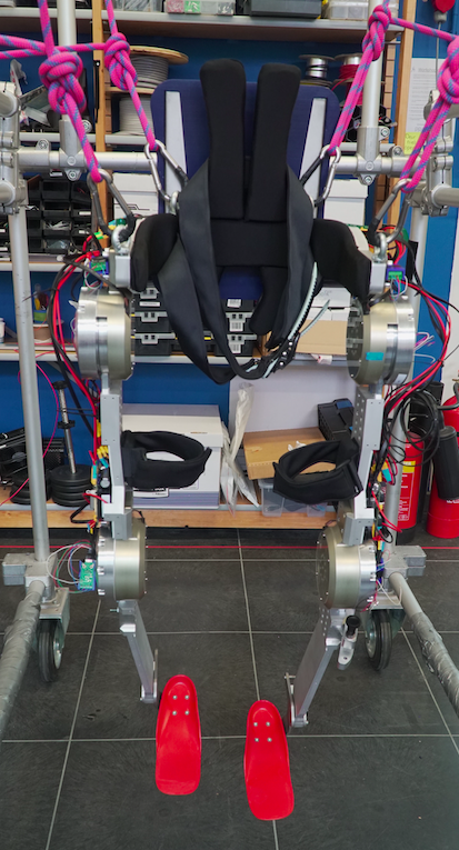
Figure: Frame of the third MARCH exoskeleton
After building these two exoskeletons with quite complicated frames, it was time to rethink the frame design. The fourth team continued working with the pilot of the third team and had similar challenges concerning lack of space for the electronics, but they also had an additional challenge. This exoskeleton would be built in a year, just like all the other ones, but it would be used and improved by the succeeding team. This meant that they would have to build an exoskeleton that could be easily adapted and is very modular. To do this, the bones became very simple compared to the years before and lost most of their multifunctional properties. These functions were taken over by 3D printed parts placed around the bones, for instance.
Instead of incorporating a method for adjustability, it was chosen to manufacture multiple sizes of the bones. If the chosen bone was too long or short, it could simply be swapped for a different size. This method, combined with fewer functionalities and aluminium as the chosen method, resulted in very simple designs that could be manufactured very easily.
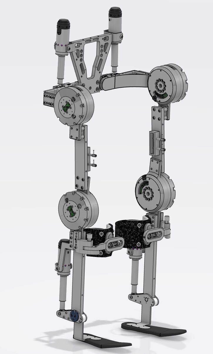
Figure: Visualization of the frame of the fourth MARCH exoskeleton
There you have it, the basics of the Project MARCH frame evolution. As you can see, changing design requirements can result in frames that are completely different from each other and yet all be compatible for a well functioning exoskeleton. In the next few years, new insights in materials and structures and changing wishes and requirements will probably lead to very diverse solutions for the frame design.

Project MARCH: behind the technology of robotic exoskeletons by TU Delft OpenCourseWare is licensed under a Creative Commons Attribution-NonCommercial-ShareAlike 4.0 International License.
Based on a work at https://online-learning.tudelft.nl/courses/project-march-behind-the-technology-of-robotic-exoskeletons/