


Structural Stiffness Concept
Course subject(s)
2. Axial Loaded Members
We have previously derived the force-displacement relation for axial loaded members as:
\[\delta=\frac{PL}{EA} \]
This, however, is not directly applicable to all common axial loaded members in engineering. Take for instance the steel cable and spring shown below.
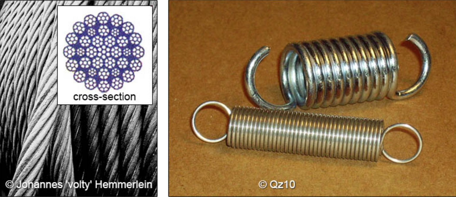
Determining the precise cross-sectional area of the cable is not trivial, and the individual strands of the cable are typically twisted, and thus not perfectly straight. Looking at the spring, it is much more complicated as a spring is actually a helical beam! But we use both of these structures commonly as axial loaded members, so it is convenient to treat them as such in design. Plus they are “off-the-shelf” components, meaning we typically do not design a spring or cable for a given application. We select them out of the offerings of a supplier.
Rather than calculating the force-deflection behaviour, we can also measure it. The slope of this curve is the structural stiffness, and comprises of both material and geometrical influences.
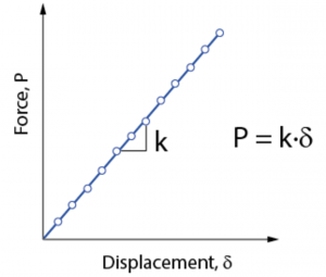
This is commonly done for springs, where the results are given directly as the slope of the force-deflection curve, k. For cables, it is common to back-calculate an effective area (Aeff) of the cable, as k is a function of cable length.
\[P_{axial rod}=\frac{EA}{L}\delta \]
\[P_{spring}=\frac{EA_{eff}}{L}\delta \]
\[P_{cable}=k\delta \]

Aerospace Mechanics of Materials by TU Delft OpenCourseWare is licensed under a Creative Commons Attribution-NonCommercial-ShareAlike 4.0 International License.
Based on a work at https://ocw.tudelft.nl/courses/aerospace-mechancis-of-materials/.