


7.2.4 Example of a Joint Analysis
Course subject(s)
Module 7. Joining of Structures and Manufacturing
In this section, we will take you through a worked out example of a joint analysis.
In this example we calculate the critical static failure mode (excluding fastener pull out) and whether the design is sufficient for the given loading.
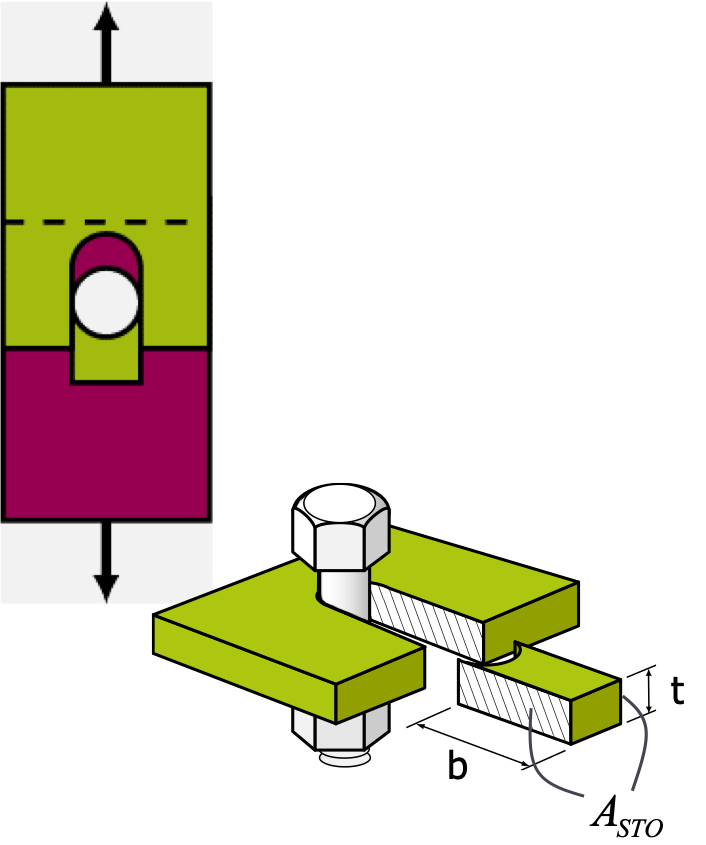
Two sheets made of t = 1 mm thick 2024-T3 aluminium are riveted together using three rows of rivets, spaced 25 mm apart both horizontally and vertically. The first and third row of rivets are 15 mm away from the edges of the sheets and the width of the sheets is 100 mm. The rivets have a diameter of 3.5 mm. The sheet is loaded by a force F = 18 kN and a resulting normal stress 𝜎 = 180 MPa.
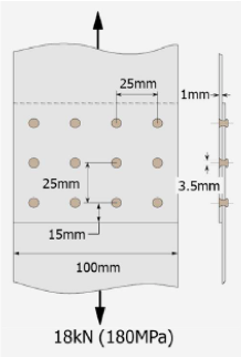
The maximum stresses in the 2024-T3 sheet material are:
-𝜎𝑡𝑢 =430𝑀𝑃𝑎
-𝜏𝑠𝑢 =270𝑀𝑃𝑎
-𝜎𝑏𝑟 =500𝑀𝑃𝑎
The maximum shear stress of the bolt is:
𝜏𝑠,𝑏𝑜𝑙𝑡 =180𝑀𝑃𝑎
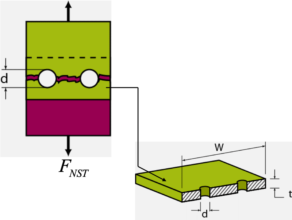
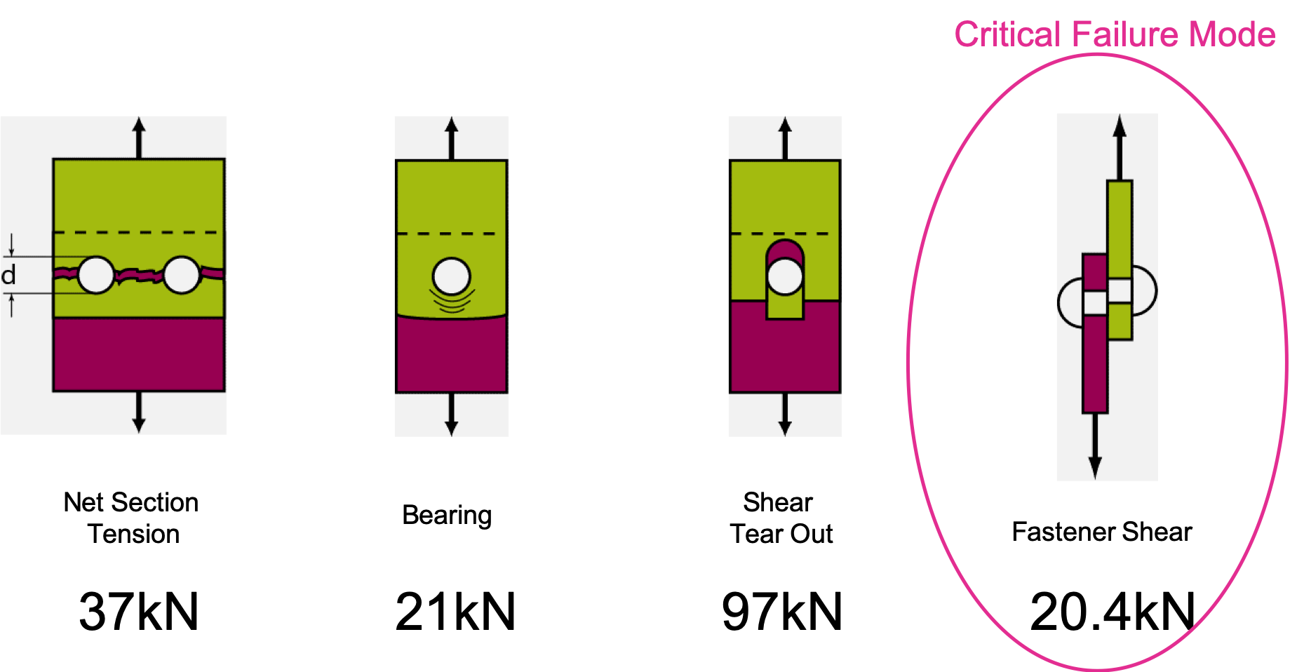
As 37𝑘𝑁>18𝑘𝑁, NO Net Section Failure will occur.
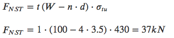
𝐹𝑏𝑟=𝑑.𝑡.𝜎𝑏𝑟 =3.5.1.500=1.75𝑘𝑁 per rivet.
There are 12 rivets, hence for bearing failure to occur the entire load on the joint must be equal to:
1.75⋅12=21𝑘𝑁
As
21𝑘𝑁>18𝑘𝑁, NO Bearing Load Failure will occur.
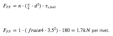
There are 12 rivets so the load that can be carried by all 12 rivets together in this joint is equal to: 1.7𝑘𝑁⋅12=20.4𝑘𝑁.
As 20.4𝑘𝑁>18𝑘𝑁, NO Fastener Failure occurs either.
Summary
Summarizing, we can say that al failure loads exceed the design load of 18 kN but that with 20.4 kN, Fastener Shear Failure is the Critical Failure Mode for this joint.

Introduction to Aerospace Structures and Materials by TU Delft OpenCourseWare is licensed under a Creative Commons Attribution-NonCommercial-ShareAlike 4.0 International License.
Based on a work at https://online-learning.tudelft.nl/courses/introduction-to-aerospace-structures-and-materials/.